
In previous articles we have seen some details of how the Kubernetes architecture is built.
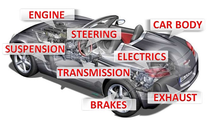
Today the working mechanisms of the Kubernetes engine will be described indicating the name of each component; to remain faithful to the comparison of the car engine, we will speak of the camshafts, valves, bearings, … that belong to the Cloud Native
Note 1: The installation of k8s in Datacenter, Cloud, and Laboratory will not be discussed, the network has already made comprehensive tutorials available.
To familiarize yourself with k8s I recommend using Minikube (Linux platform) Docker Desktop (Windows & Mac platform).
Let’s begin!
Kubernetes Master:It is the main node of the cluster on which three processes that are vital for the existence of the cluster run.
- kube-apiserver
- kube-controller-manager
- Kube-scheduler
In the master node, there is also the DataBase etcd, which stores all configurations created in the cluster.
The nodes that take care of running the applications and therefore the services are said worker node. The processes present on the worker node I’m:
- Kubelet
- kube-proxy
kubectl : AND’ The official Kubernetes client ( CLI ) through which you can manage the cluster ( Kube-apiserver ) using the API.
Some simple examples of kubectl commands are:
- kubectl version (indicates the version of k8s installed)
- kubectl get nodes (find out the number of nodes in the cluster)
- kubectl describe nodes nodes-1 (shows the health status of the node, the platform on which k8s is running (Google, AWS, ….) and the allocated resources (CPU, RAM)).
Kube-Proxy : He is responsible for managing networking, from Routing to Load Balancing rules.
Note 2 : K8s will try to use them all libraries available at the level of operating system .
Container Runtime : It is the foundation on which the k8s technology rests.
kubernetes supports several runtimes among which we remember, container-d , cri-o , rktlet .
Note 3 : The runtime Docker it has been deprecated in favor of those that use interfaces CRI ; Docker images will still continue to work in the cluster.
The objects Kubernetes base are:
- Pod
- Services
- Volumes
- Namespace
THE controller provide additional functionality and are:
- ReplicaSet
- Deployment
- StatefulSet
- DaemonSet
- Job
Between Deployment it is imperative to mention Kube-DNS which provides name resolution services. Since kubernetes version 1.2 the name has changed to Core-dns.
Add-On : they are used to configure further cluster functions and are placed inside the name space kube-system (such as Kube-Proxy, Kube-DNS, kube-Dashboard)
Add-ons are categorized according to their use:
- Add-on of Netwok policy . (For example the NSX-T add-on takes care of the communication between the K8s environment and VMware)
- Add-on Infrastructural (For example KubeVirt which allows connection with virtual architectures)
- Add-on of Visualization and Control (For example Dashboard a web interface for K8s).
For commissioning, Add-ons use controllers DaemonSet And Deployment .
The image in figure 1 summarizes what has just been explained.
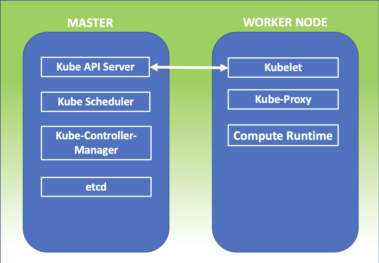 Figure 1
Take care and see you soon.

 Figure 1
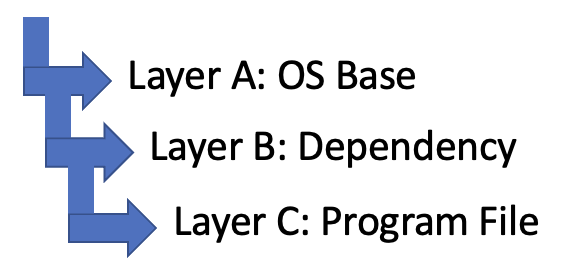 Figure 2
 Figure 3
 Picture 1
 Image 2