
On November 23, 2021, the new version of the Veeam Disaster Recovery Orchestrator was released.
The list of new features introduced in version 5 is available by clicking here.
Today we will deal with the phase immediately following installation; specifically, the configuration and commissioning phase.
After logging in (it is mandatory that the user has already joined the Domain – Image 1 and 2)
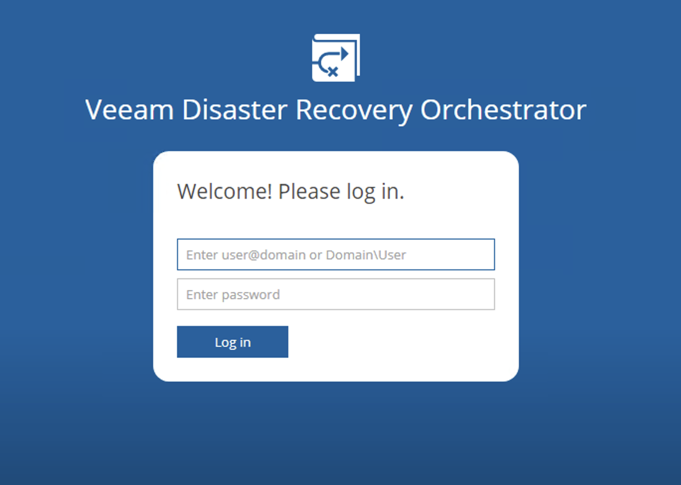 Picture 1
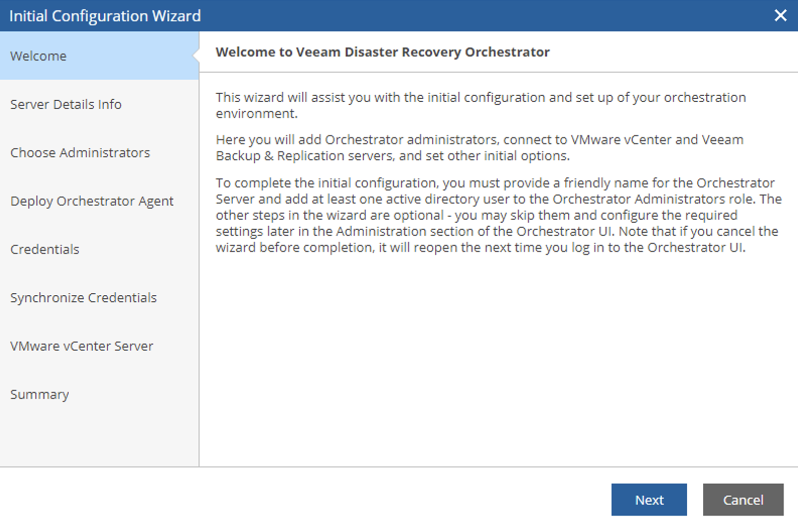 picture 2
The wizard allows you to add and define:
- The Name of the Orchestrator Server (Image 3)
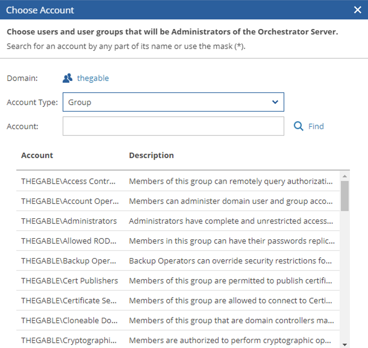
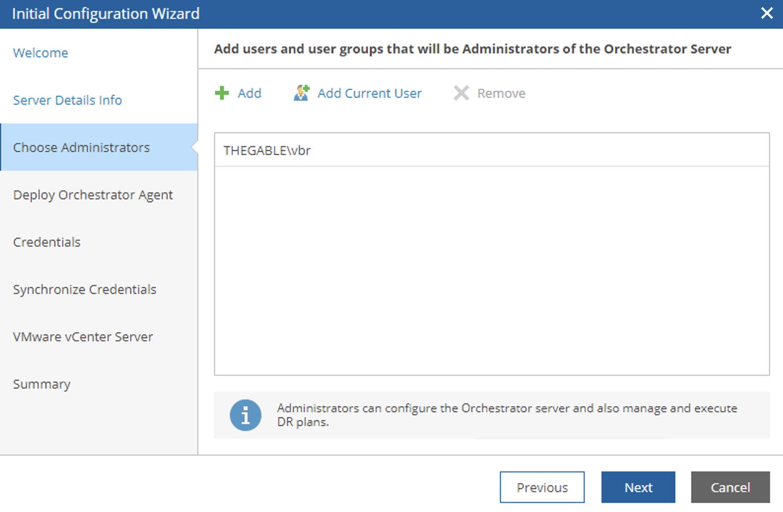
- The admin account or group of accounts (image 4, 5 and 6)
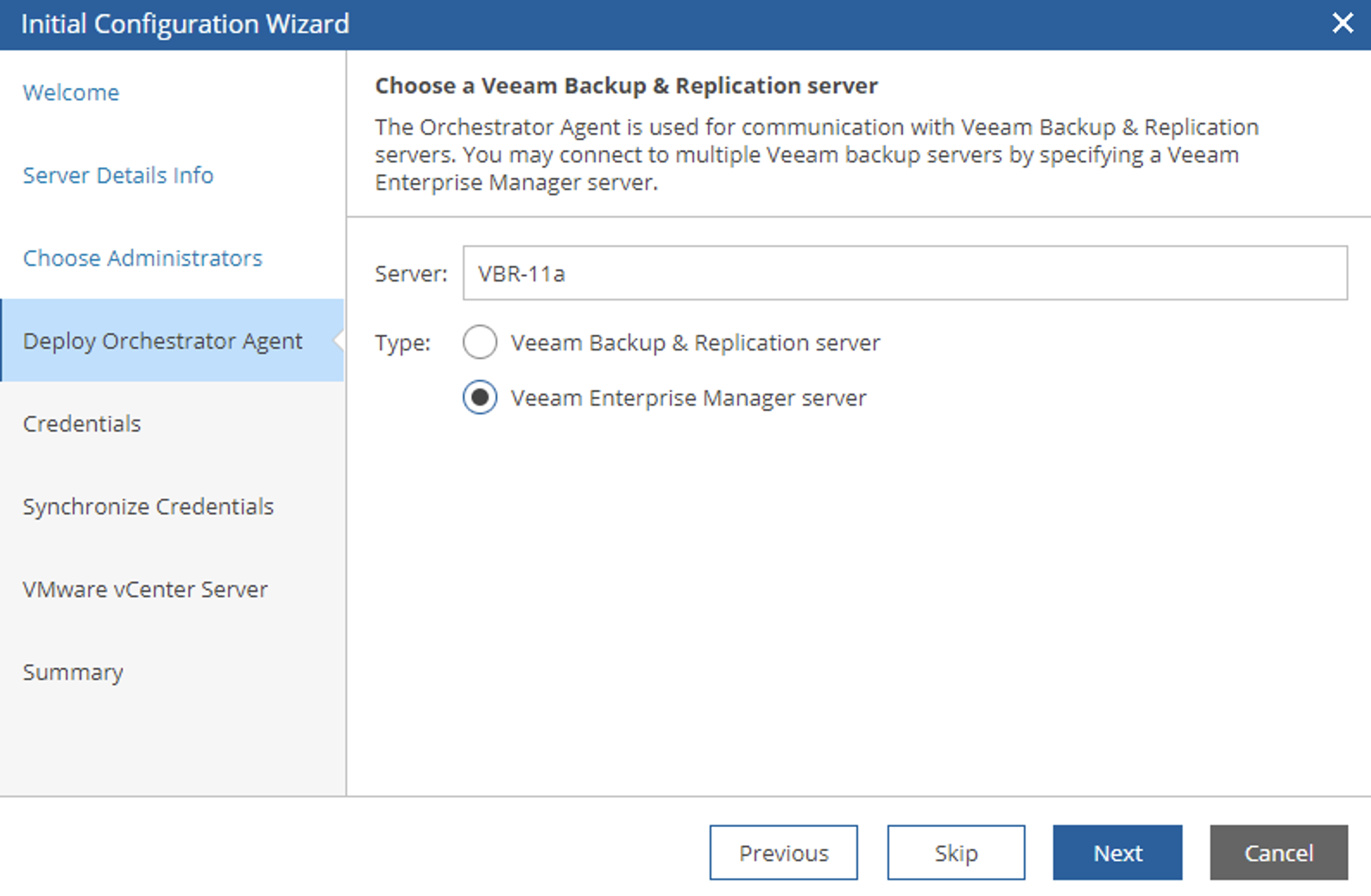
- The Backup Servers that will communicate with the Orchestrator Server through a specific agent (image 6, 7 and 8)
- The vCenters that will be commanded to start the Disaster Recovery plans (Image 10)
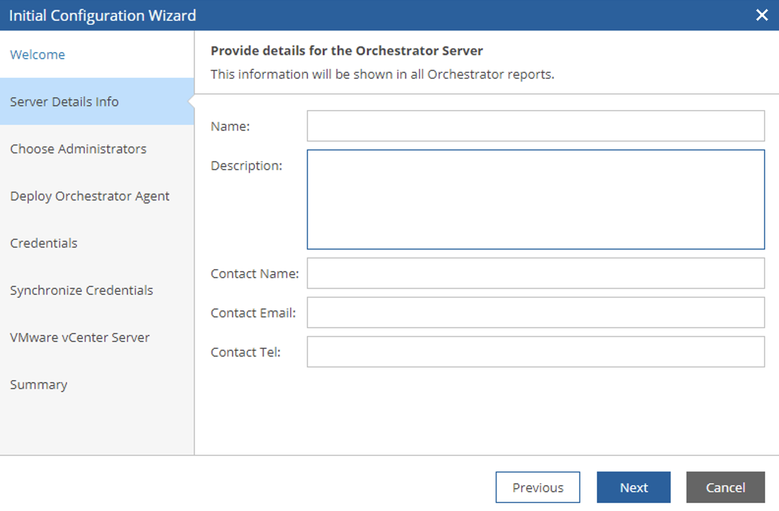 Picture 3
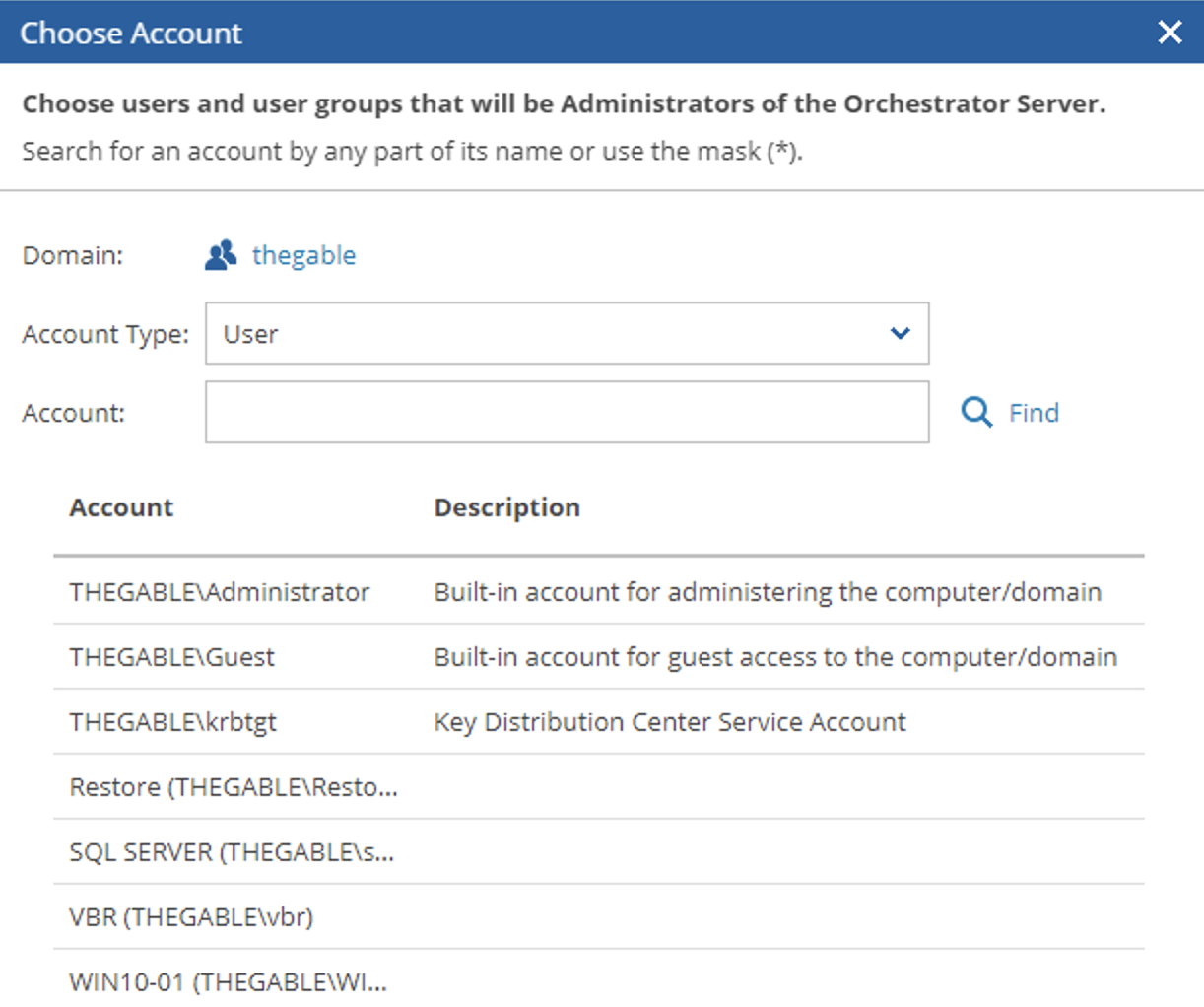 Picture 4
 Picture 5
 Picture 6
 Picture 7
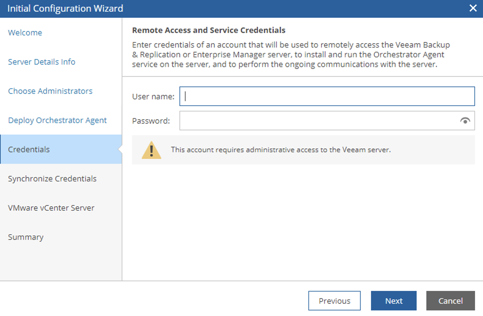 Image 8
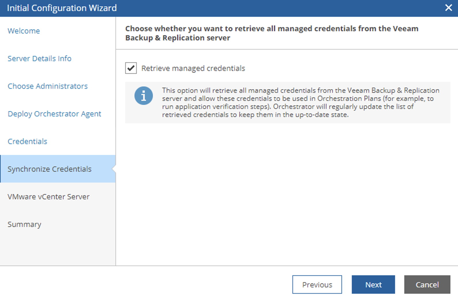 Image 9
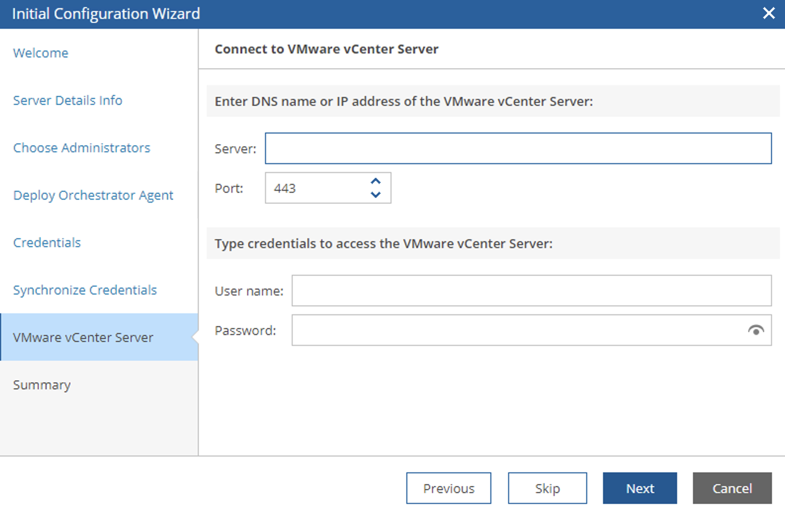 Image 10
In the next article, I’m going to illustrate the steps to create a Disaster Recovery Plan with this new version of the Veeam Disaster Recovery Orchestratrion
See you Soon!