A virtual LAN (vLAN) is any broadcast domain that is partitioned and isolated in a computer network at the data link layer (OSI layer 2) (wikipedia)
vLANs works by applying tags to network frames and handling these tags in networking systems.
——
I love how USG has faced up the vLAN challenge.
Their starting point is working with vLAN as if it were a layer 3 object and not layer 2 of the OSI model.
The idea behind USG is thinking vLAN is a new LAN with a different IP Address”. Are you a little bit confused? Yes? I also was at the beginning but now I’m enthusiastic of this new approach.
Let’s explain better with an example directly from my Lab Network.
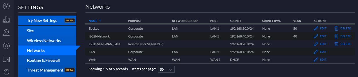
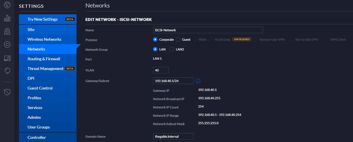
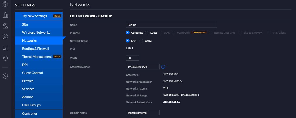
In my Environment I needed to create 2 vLAN. The first one to address the iSCSI protocol and the second to manage the Backup traffic.
I chose #40 to point up iSCSI vLAN and #50 the Backup.
I went directly to USG user interface and created the vLANs from Network menu as shown in figure 1, 2 and 3
Figure 1
Figure 2
Figure 3
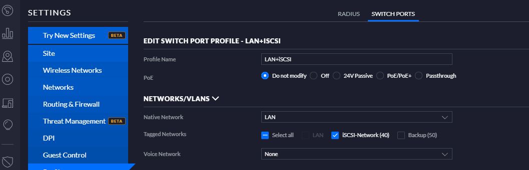
The next step is enabling routing between the new networks and the original LAN.
The task is performing selecting Switch ports from Profiles Menu.
As shown on figure 4 I set up an easy rule to let the networks talk to “each other”. In this case LAN to iSCSI as Figure 4
Figure 4
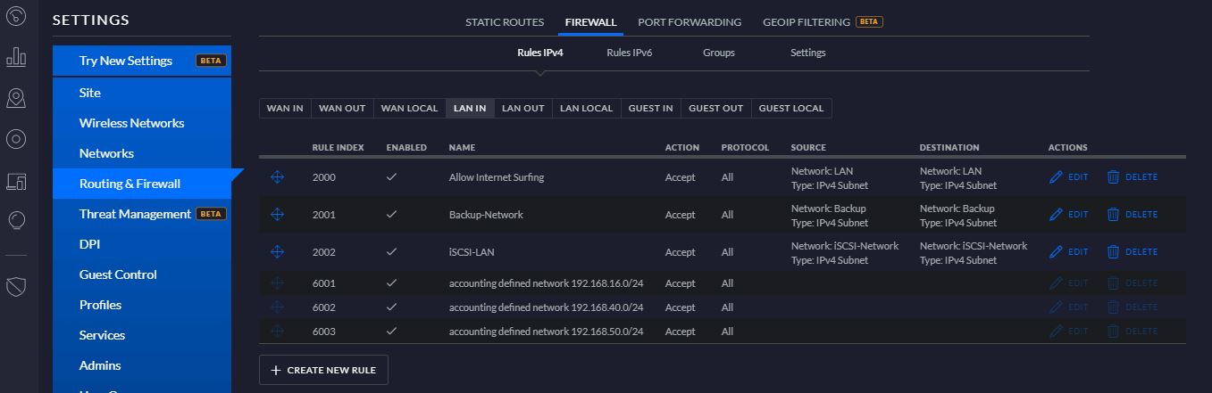
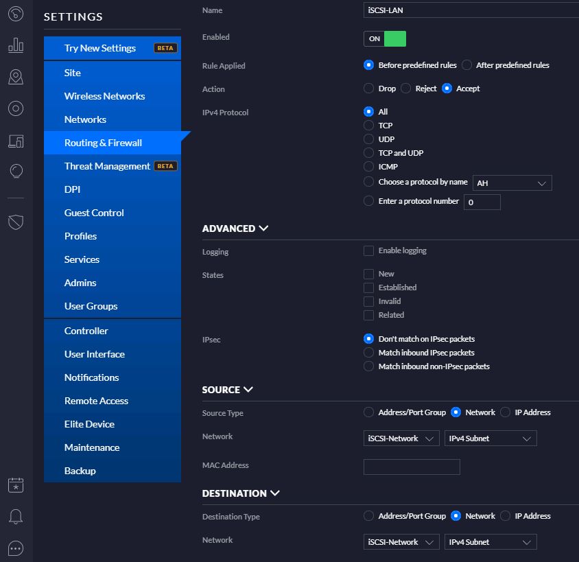
Now the last step. Enabling traffic from and to the Networks. In a simple word I worked at Firewall level.
I spent some hours to understand the options the USG can offer to their customers because it’s possible to set up many rules to manage traffic among LAN (LAN-IN and OUT), WAN (WAN-IN and OUT), GUEST (IN and OUT) and LOCAL (WAN/LAN/GUEST)
Really many many options but with a little patience, you can tune your networks answering to any security design.
In this example, I just created rules to manage the traffic LAN IN (FIGURE 5 and 6)
FIGURE 5
FIGURE 6
Before ending this article two more notes:
If you want to grant the Servers connected to LAN to surf on Internet, you just need to set up a LAN-IN and a LAN-OUT rule.
To work with vLAN you need to buy an Ethernet Switch vLAN compliant
Last device I added to my lab is the Ubiquity Unify Security Gateway (from now on USG)
I need it because I have to work with a great number of vLAN in my demo lab.
Let’s see what I learned in the last test weeks and how I set it up to address my needs.
The hardware installation is quite easy. After unpacking the box you just need to plug-in the power supply and two ethernet cables, the first one on LAN Port and the second to WAN port.
The USG setup is composed of 5 configuration phases
LAN / WAN
Unifi-Controller
VPN
VLAN
Routing
In this first article, we are going to cover the three first phases.
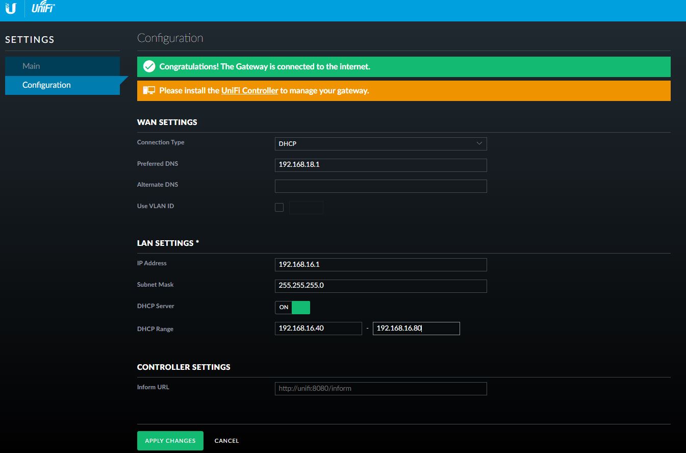
I – LAN /WAN Configuration
On your PC set up the Ethernet IP Address as 192.168.1.x/24 and plug the LAN cable. Now ping the 192.168.1.1 address to be sure you can reach the USG. Open a Browser and you’ll be able to configure LAN and WAN interfaces from 192.168.1.1 address.
Figure 1
My personal router works on 192.168.18.x while I choose to set up the LAN on 192.168.16.x address
After “applying the changes”, you have to re-change the IP address of your PC to a LAN address (192.168.16.99 for example) and test the USG answer to ping.
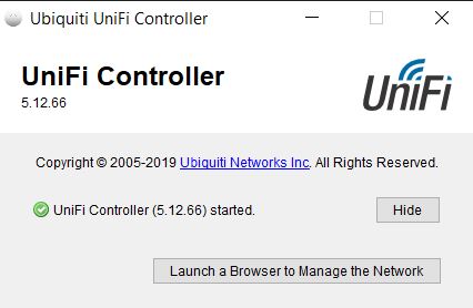
Click on “Launch a Browser to manage the network” button (Figure 2)
Figure 2
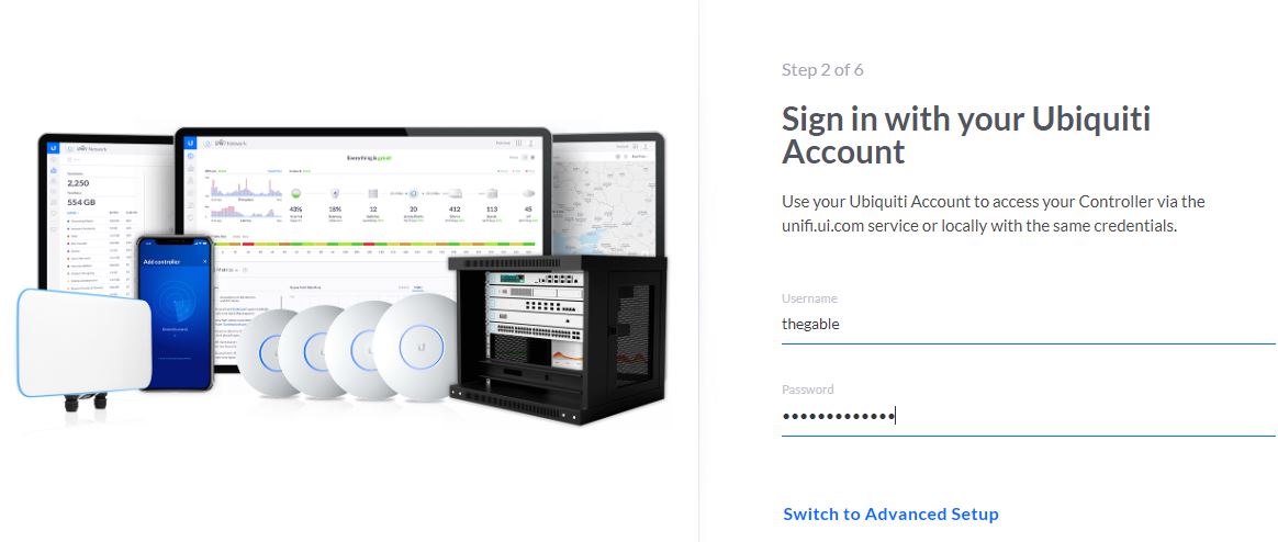
Log-in to Ubiquiti account
Figure 3
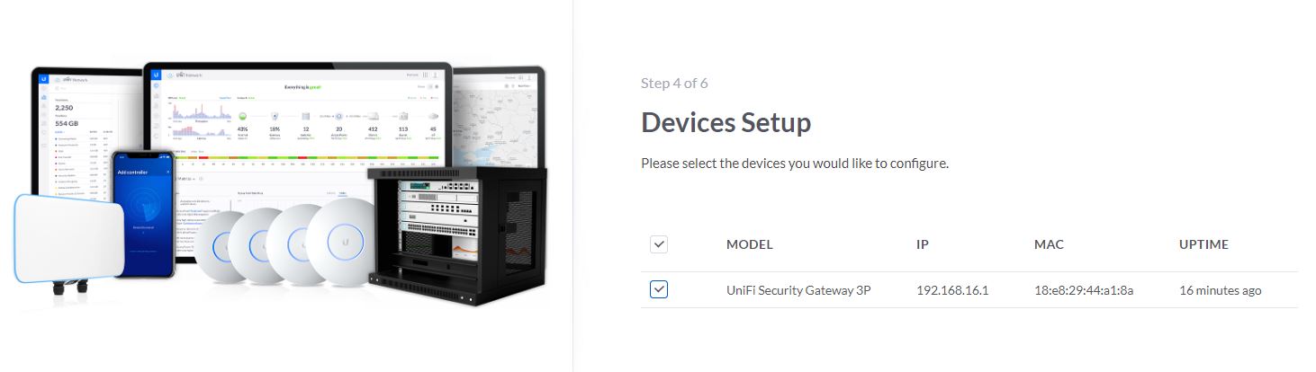
Checking if the USG device is properly discovered
Figure 4
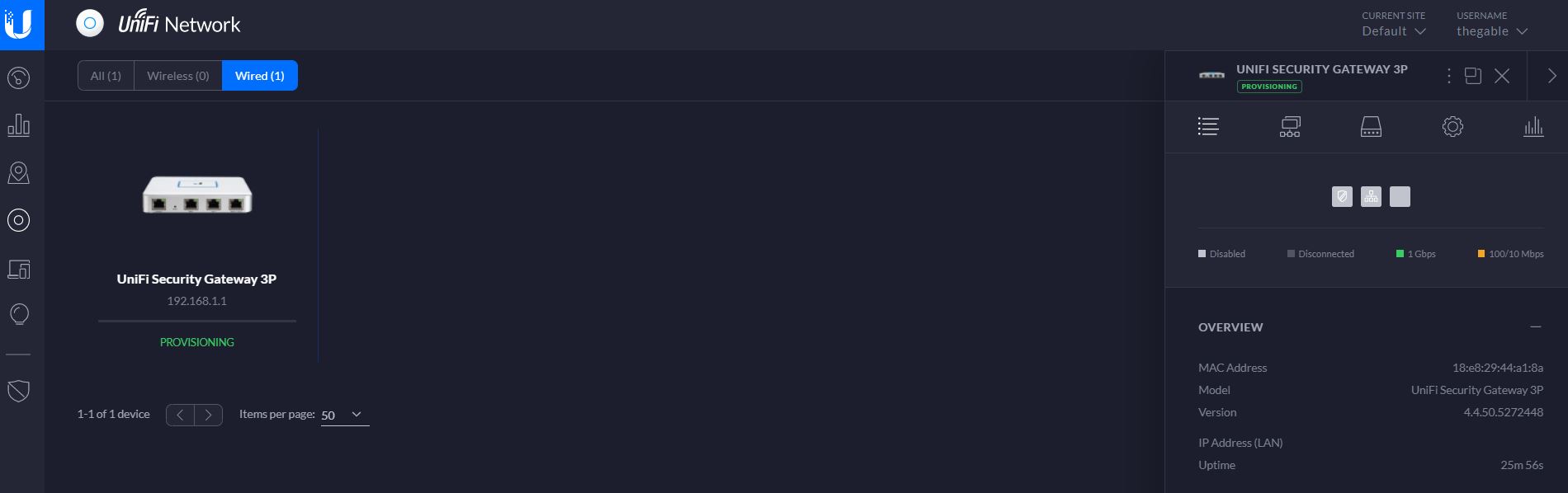
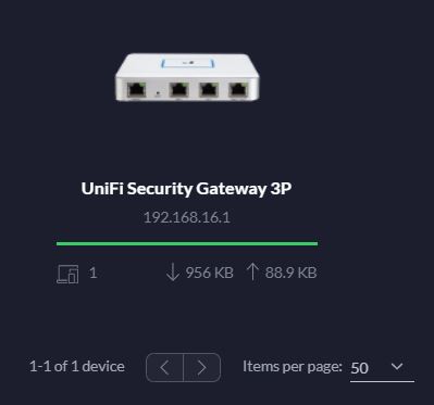
After the wizard has been completed you can start to play with the friendly user interface. Figure 5 and 6 show the USG Device status (the fourth icons on the left panel (device))
Figure 5
Figure 6
III VPN Creation
The Wizard consists in:
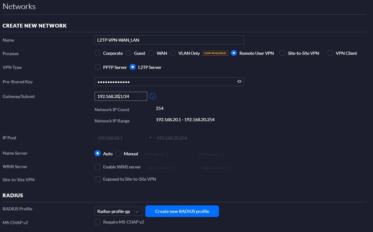
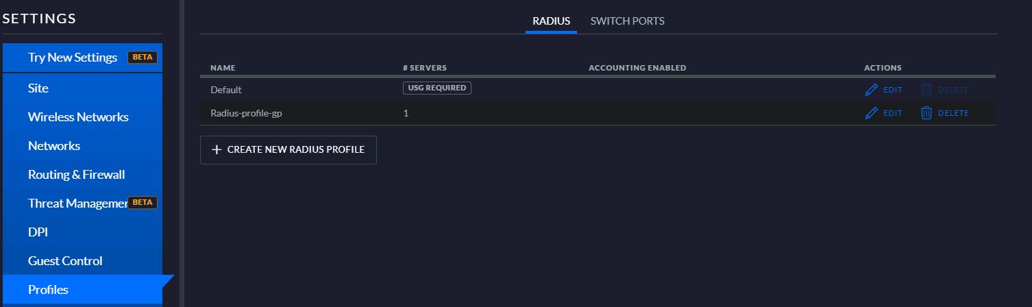
Creating a new Network (Figure 6) selecting the options “Remote user VPN” and L2PT server. On Radius menu you must add a new profile as shown in (Figure 7)
Figure 6
Figure 7
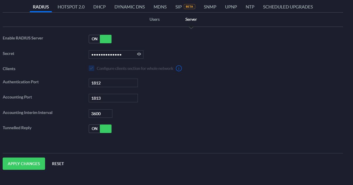
2) Enable Radius Server as shown in figure 8
Figure 8
Now you can set on your windows/linux/mac/android device the VPN connection and test it
Before ending the article two more notes.
If you see the provisioning entry on the web interface, it means USG is loading and saving the new configuration.
Le 19 squadre iscritte si incontreranno in un unico girone all’italiana di 18 incontri di 10smazzate.
Al termine si qualificheranno le prime 8 squadre.
Quarti di finale: Si sfideranno come da tabellone tennistico dove la prima squadra in classifica avrà diritto di scelta della squadra da incontrare e via di seguito. (Scelta integrale) (2 turni da 16 smazzate)
Semifinale: Le quattro squadre vincenti si sfideranno in semifinale (2 turni da 16 smazzate)
Le due squadre vincenti si sfideranno nella finalissima (2 turni da 20 smazzate).
Nella fase, in caso di parità di VP il vincitore dello scontro diretto passerà il turno.
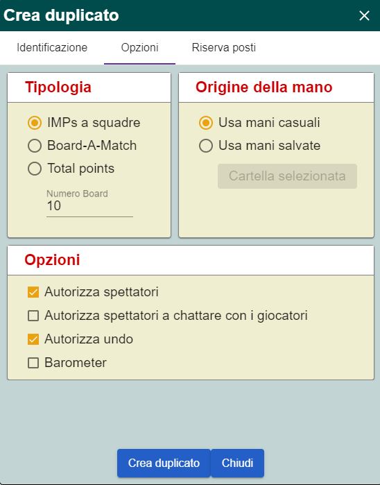
Nota bene: Durante l’organizzazione del match devono essere abilitate le seguenti opzioni:
Tipologia: IMPs a Squadre indicando il numero dei board a seconda della fase
Origine della mano: Usa mani casuali
Numero dei Board: 10 (valido per I fase)
Opzioni – Deselezionare le voci:
Autorizza spettatori a chattare con i giocatori
Barometer
L’immagine di figura 1 illustra quanto sopra esposto
Figura 1
Time frame:
Il torneo inizierà Domenica 26 Aprile e si concluderà Domenica 10 Maggio.
Per la prima fase (gironi all’italiana), ogni squadra sarà libera di accordarsi con l’avversaria per l’orario di gioco.
I 19 incontri da 10 smazzate della prima fase (girone di selezione) dovranno concludersi entro lunedì 4 Maggio 2020.
5-6 Quarti di finale – 7-8 Semifinale – 9-10 finalissima
Consolation: le squadre eliminate alla prima fase possono partecipare al danese di consolazione con formula da stabilire a seconda del numero dei partecipanti (e dalla volontà degli organizzatori, mia in particolare)