
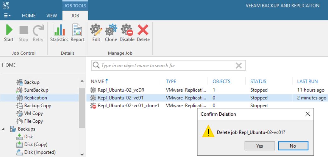
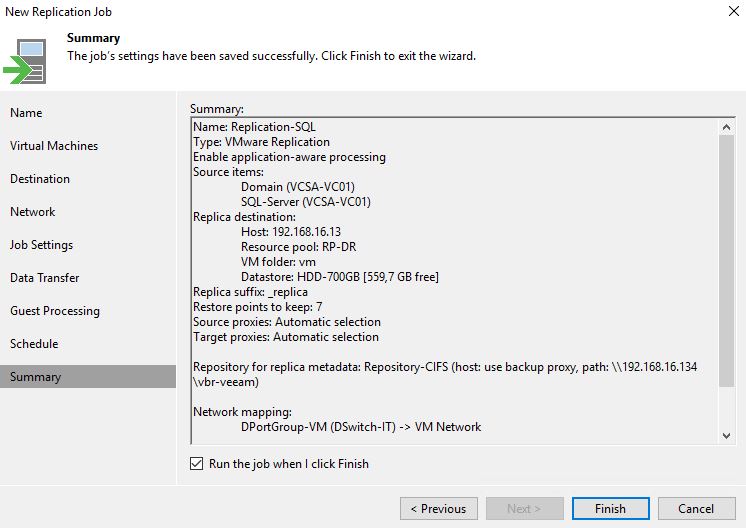
Last month, a partner had to face up a strange VBR behavior.
From the VBR console he deleted a VM’s replica (Picture 1), and suddenly the production VM has been also erased (don’t worry, before doing any activity he tested the backups using sure backup technology).
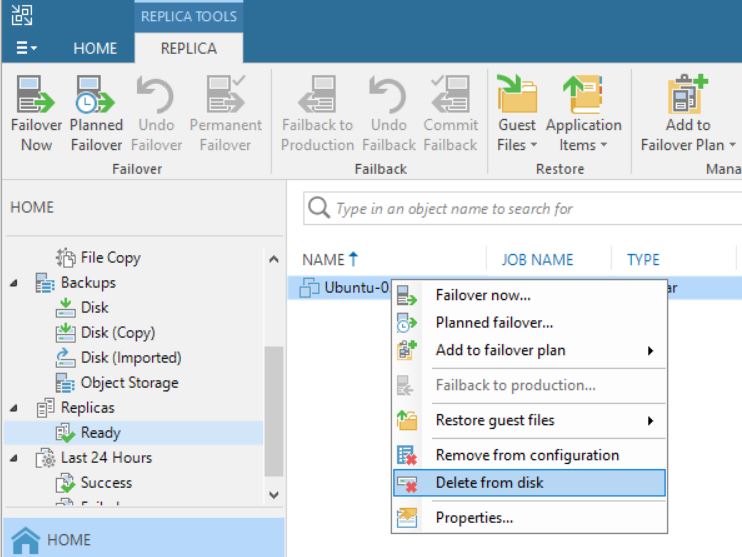 Picture 1
The reason why it happened become clear to me once I read the logs.
To do it shortly, some weeks before someone started a Failover directly from vCENTER console without doing any communication to the internal IT team.
This article wants to explain how to avoid this common mistake.
The first step is understanding some basic concepts:
a) VMware identify any single VM with a number named MorefID and a UUID.
b) Any single operating system has an identifier named Instance UUID (Universal Unique IDentifier); in my lab, I set-up more than one replica job for a single VM
Table 1. row 2. shows the name of production VM (Ubuntu-02), its morefID (vm2270), where it is running (Milan), the UUID (…bcc12) and its VM UUID … f58b.
Table 1. row 3-4 shows the name of VMs replicas, morefID, instance UUID and its UUID.
All tables shown in these articles have been created using Veeam One
| Name | PCName | morefID | DataCenter | Instance UUID | UUID | |
| Ubuntu-02 | ubuntu-02 | vm-2270 | Milan | 502d2405-cc8f-de73-1a19-57e8496bcc12 | 564d013a-7835-9d1b-841e-32855790f58b | |
| Ubuntu-02_Rep_VC01 | ubuntu-02 | vm-2694 | Milan | 502d2d90-d08f-08aa-efcf-d9feaa1d13f8 | 564d013a-7835-9d1b-841e-32855790f58b | |
| Ubuntu-02_Rep_VCDR | ubuntu-02 | vm-399 | Venice | 501d517b-672e-30e0-665a-fd4b4af7dcb6 | 564d013a-7835-9d1b-841e-32855790f58b | |
Table-1
Picture 2 shows the VM source (highlighted in yellow) from vCENTER console.
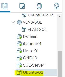
Picture 2
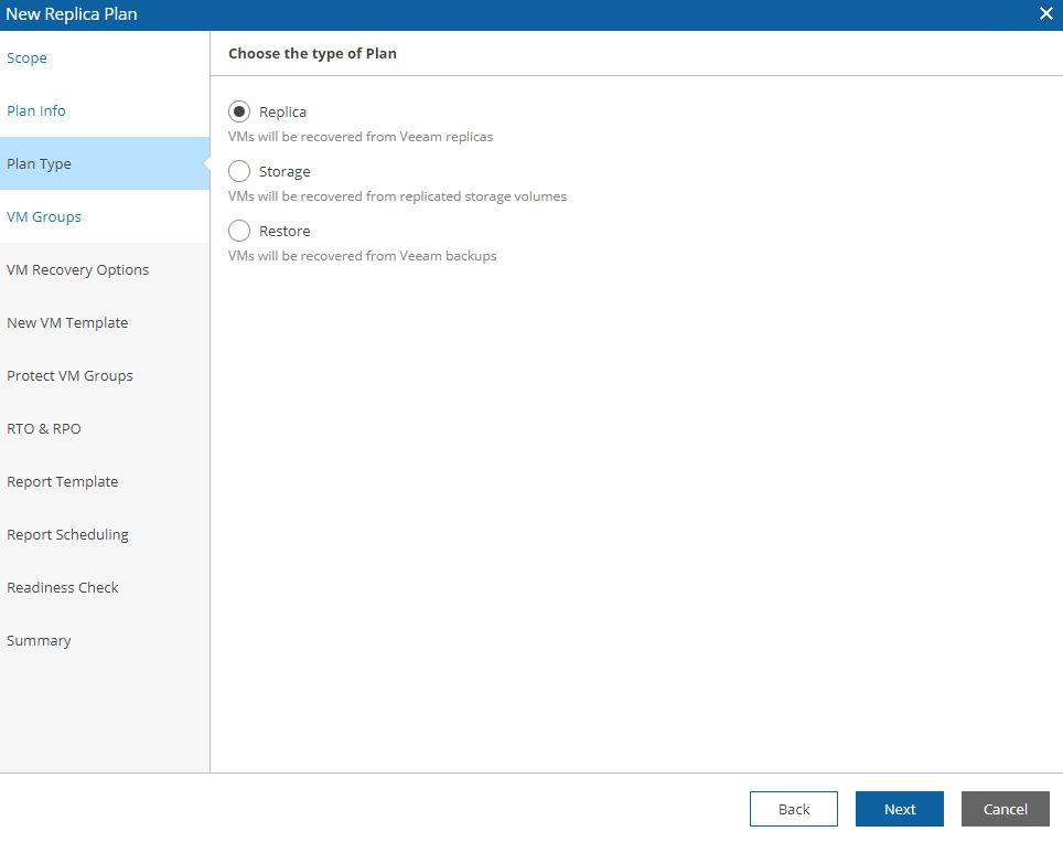
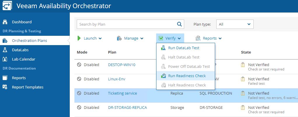
After checking up that the VM source is switched off, it’s possible to start a Failover (Picture 3).
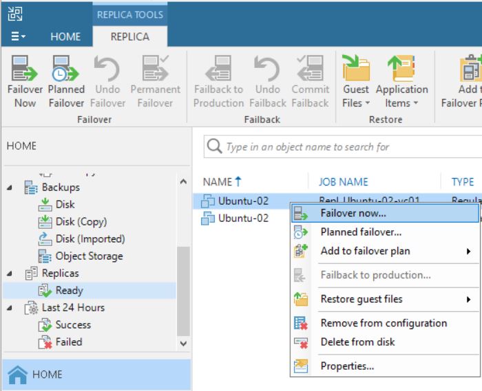 Picture 3
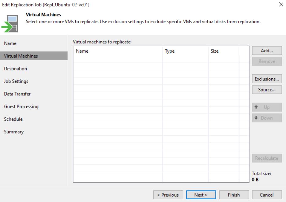
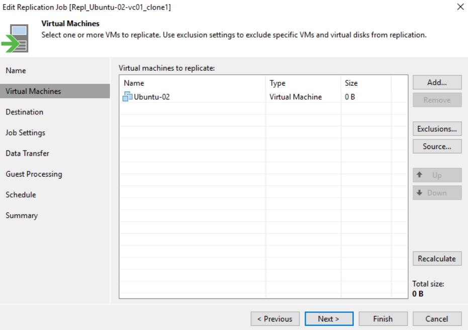
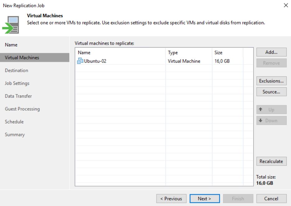
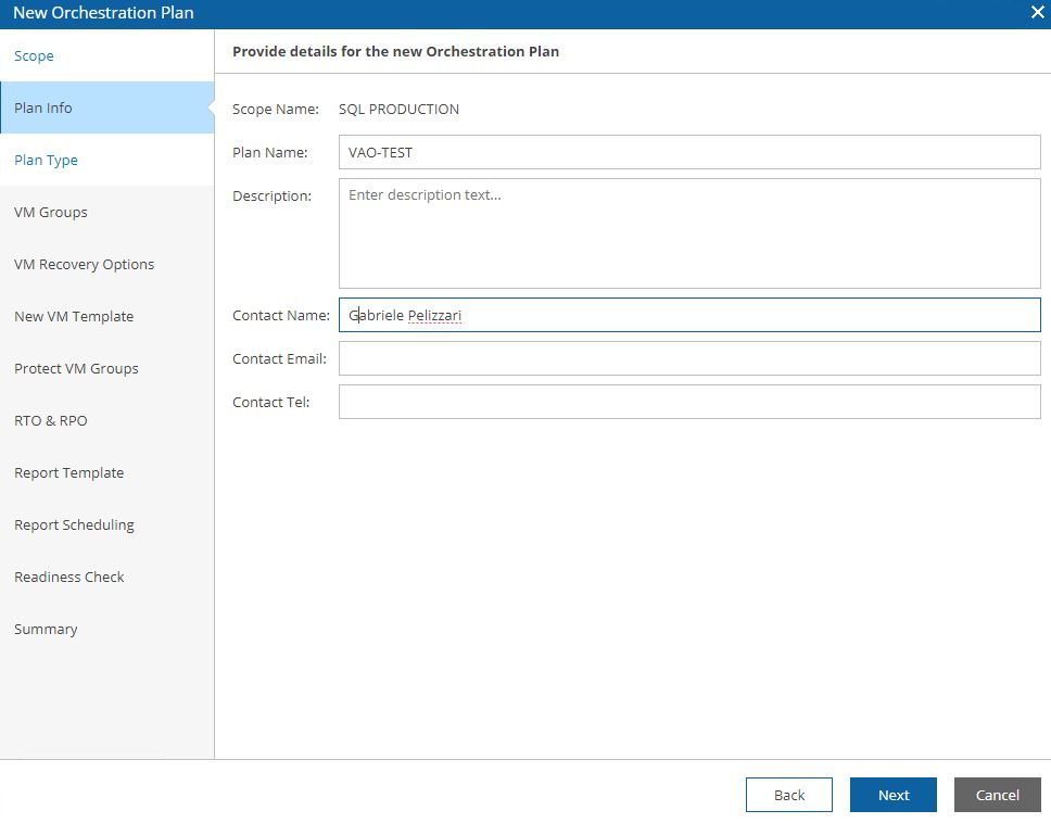
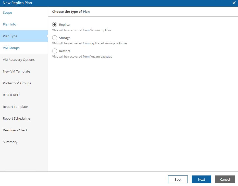
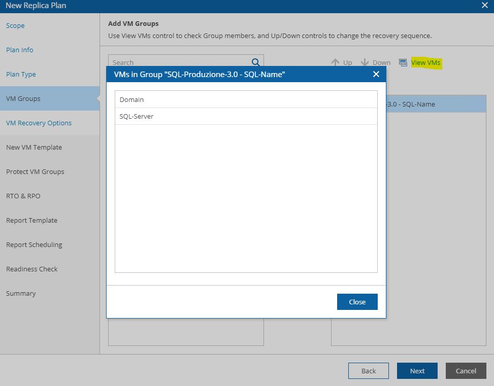
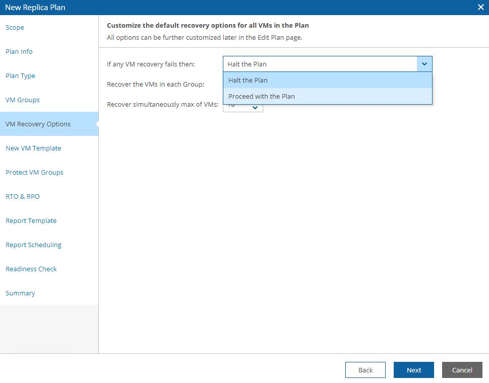
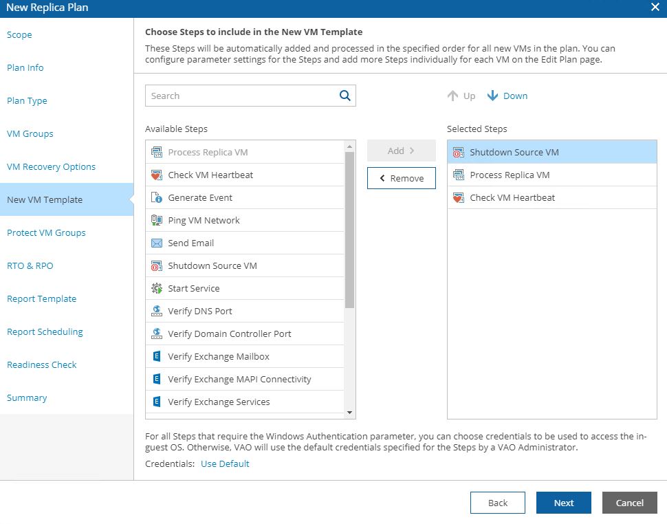
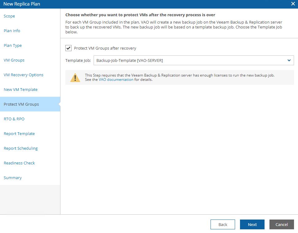
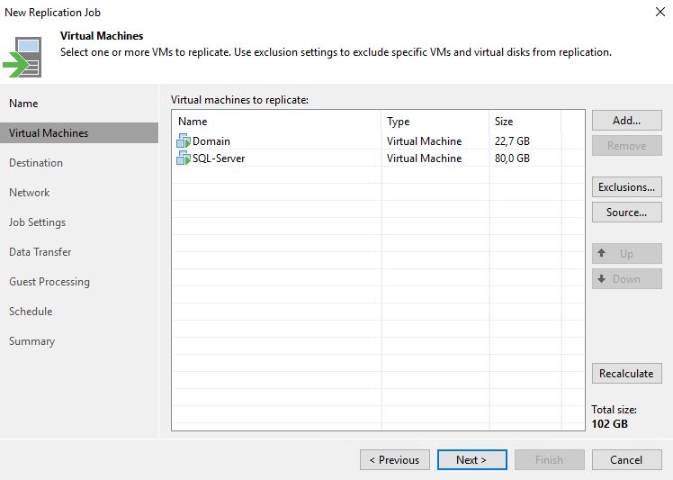
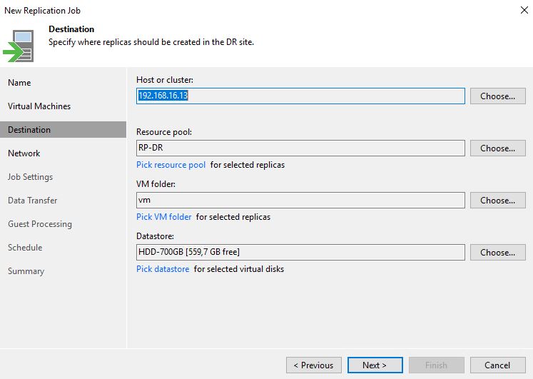
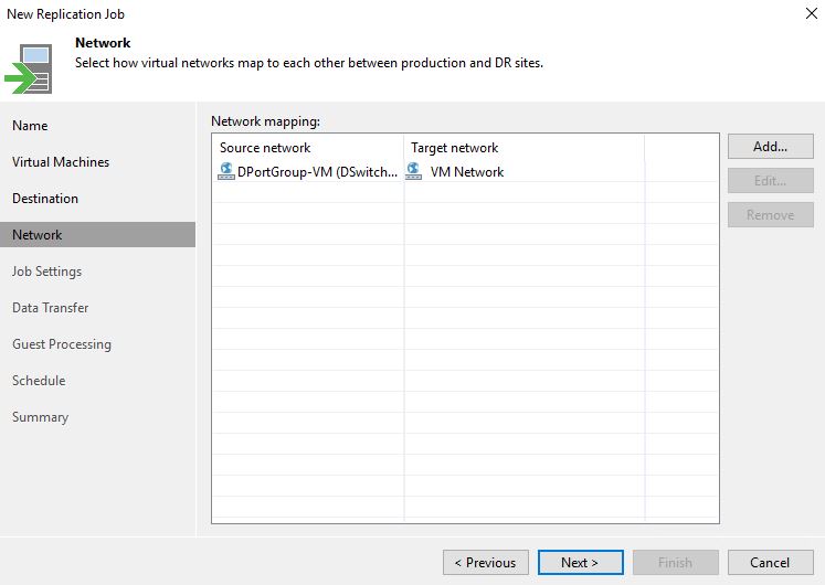
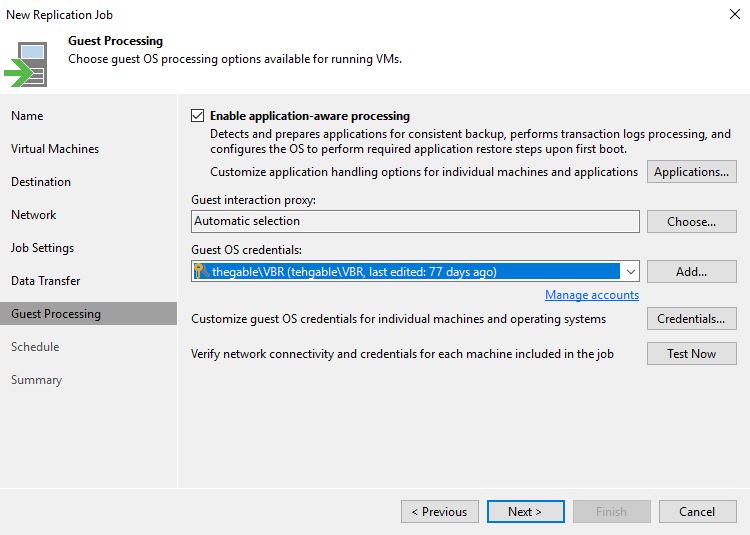
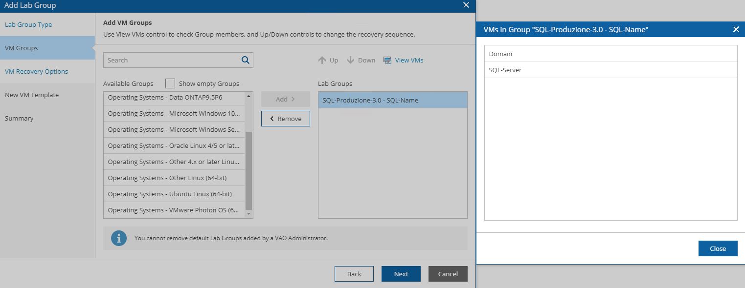
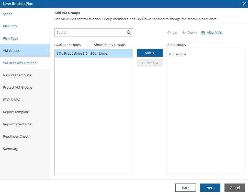
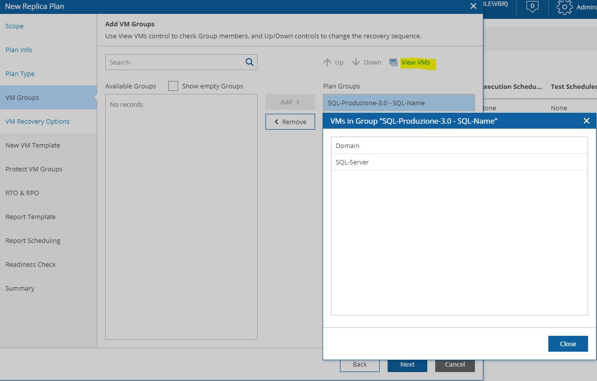
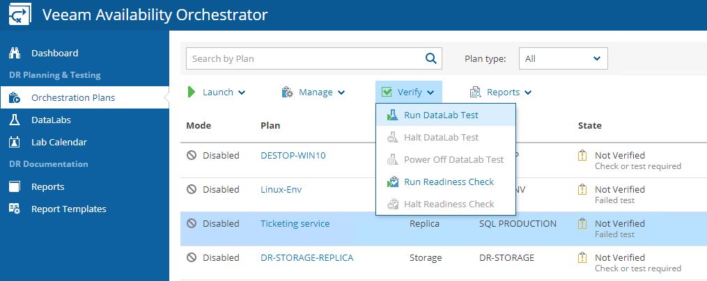
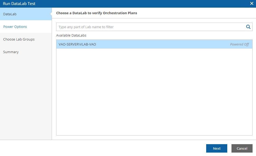
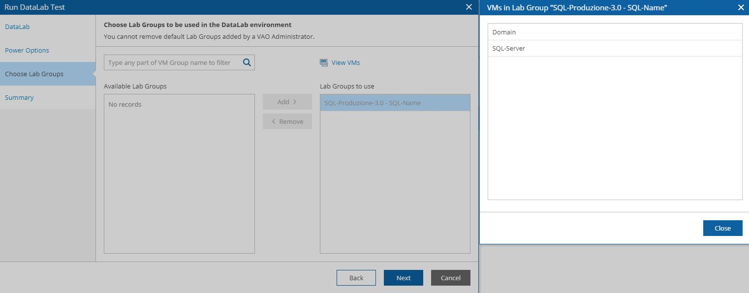
The next five pictures show the step-by-step wizard to complete the procedure correctly. As you can see from picture 4 the VM that has been replicated with two different jobs (Picture 5) is always Ubuntu-02.
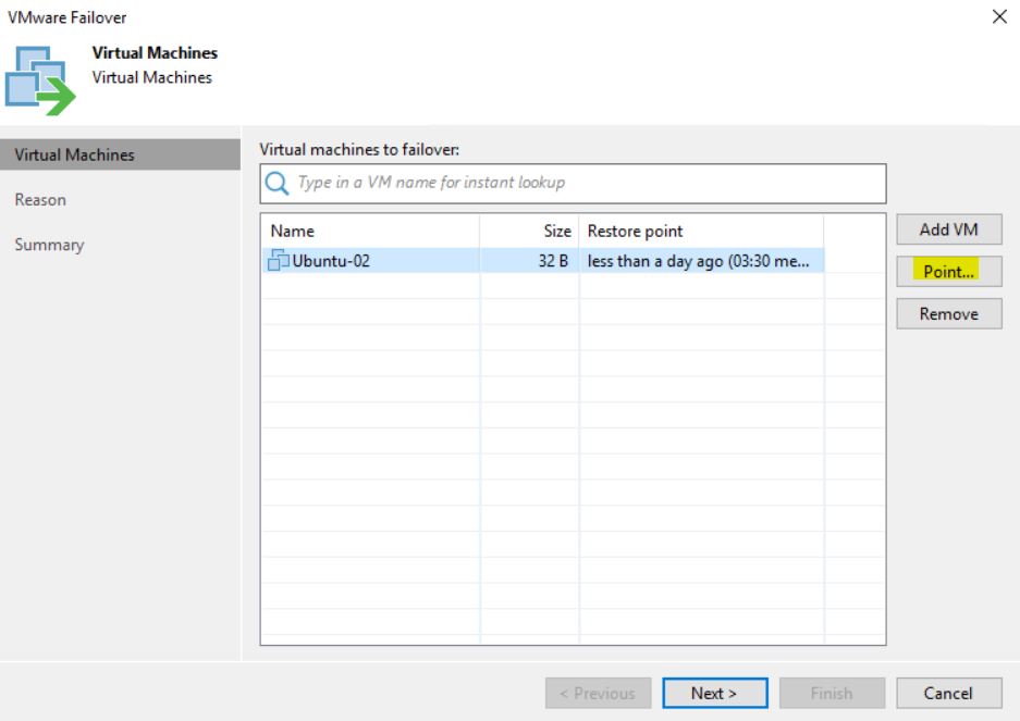 Picture 4
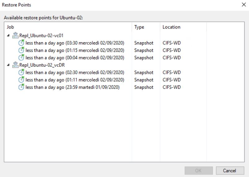 Picture 5
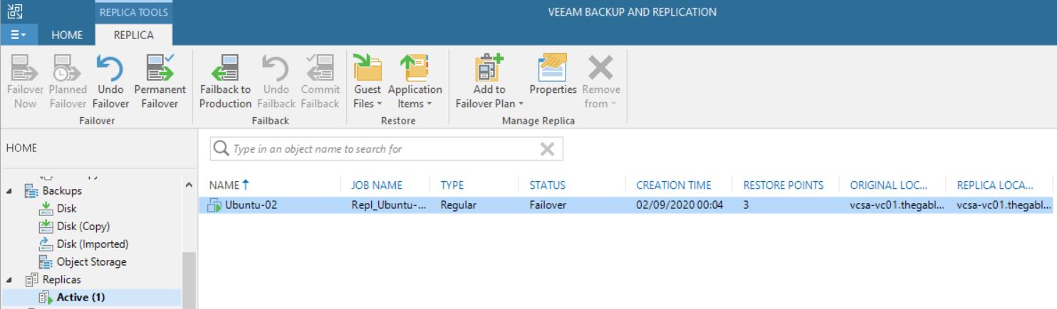
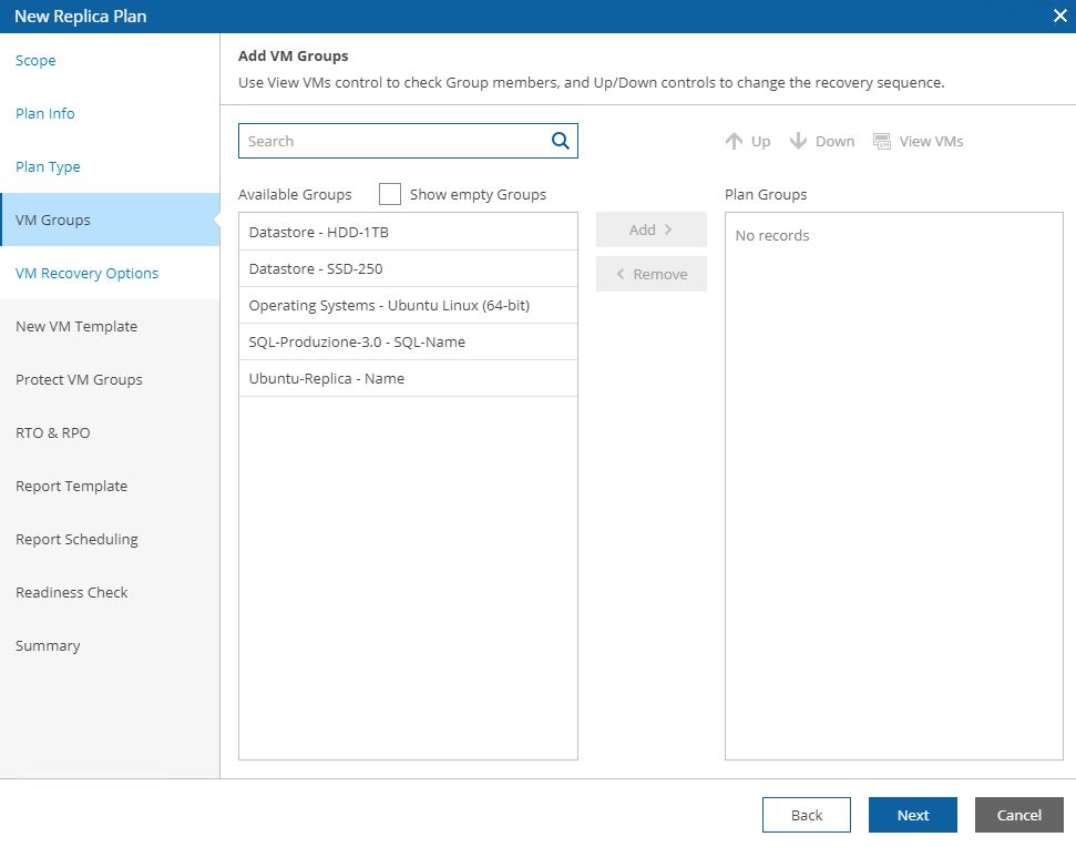
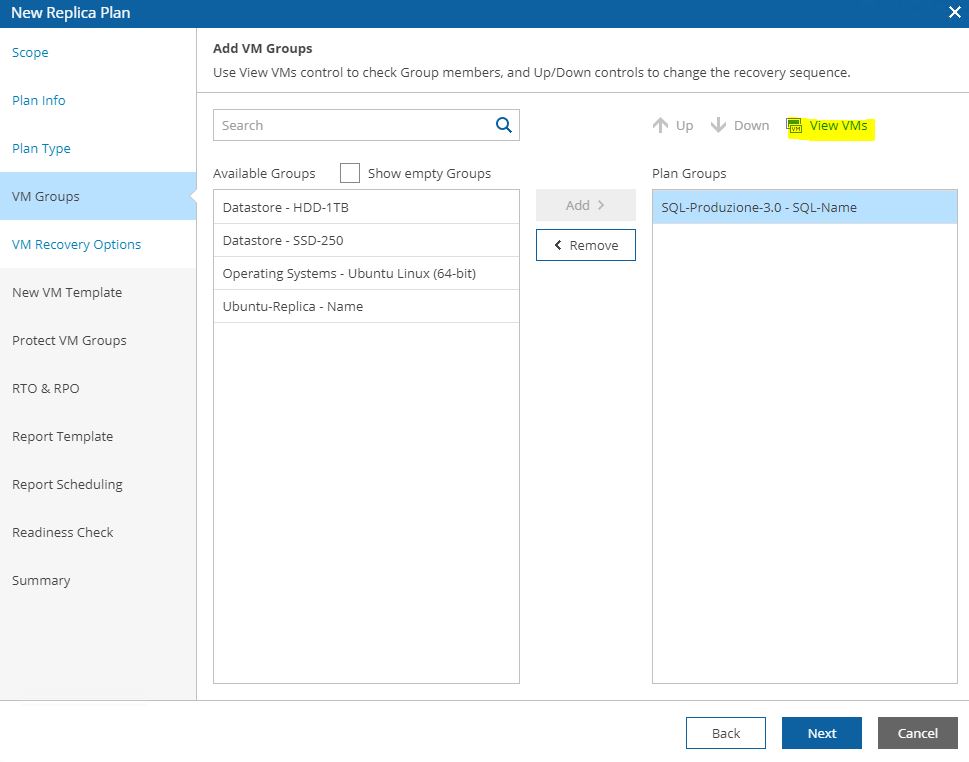
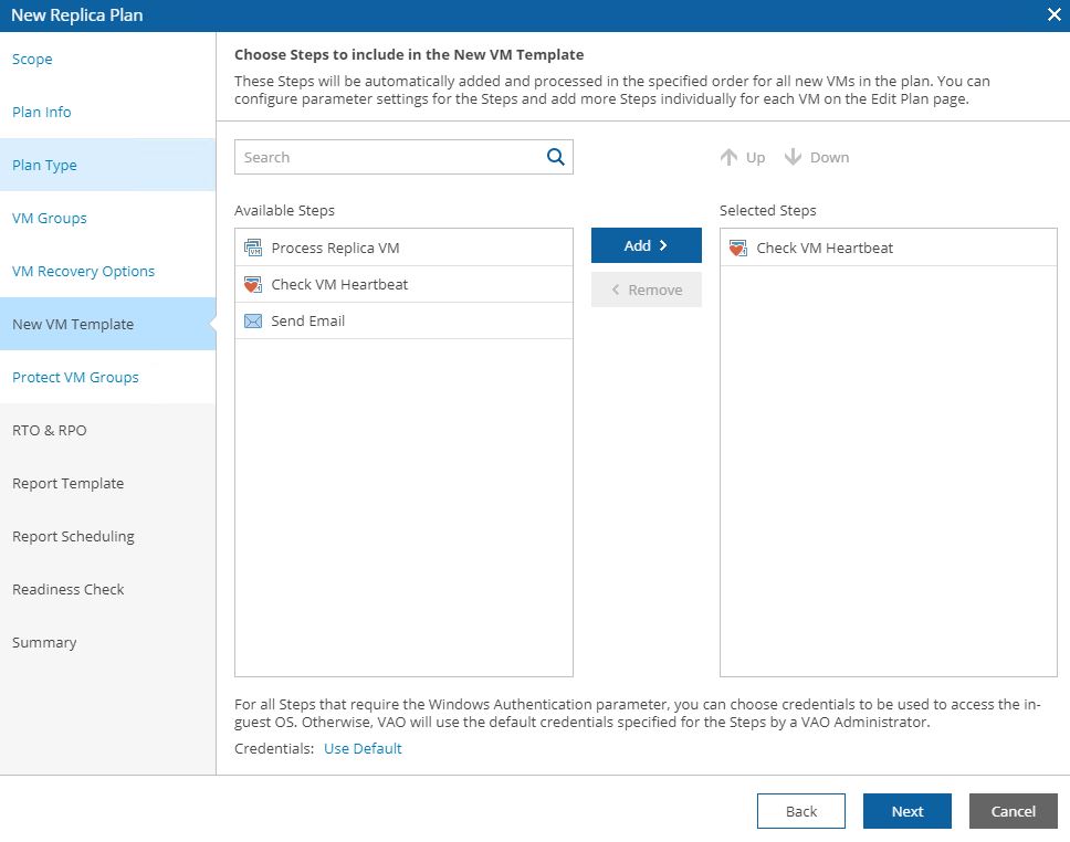
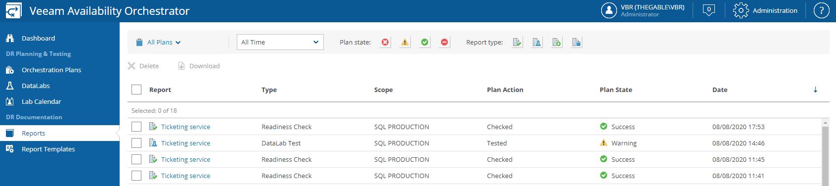
Pictures 6-8 show the result of the failover.
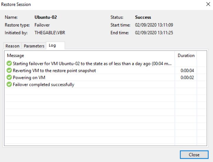 Picture 6
 Picture 7
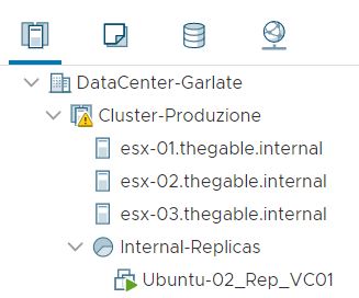 Picture 8
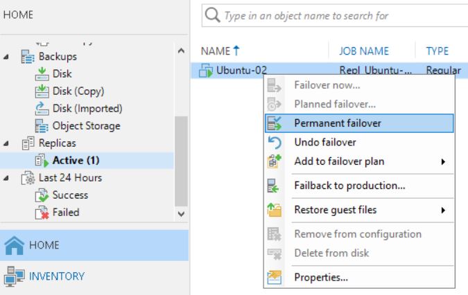
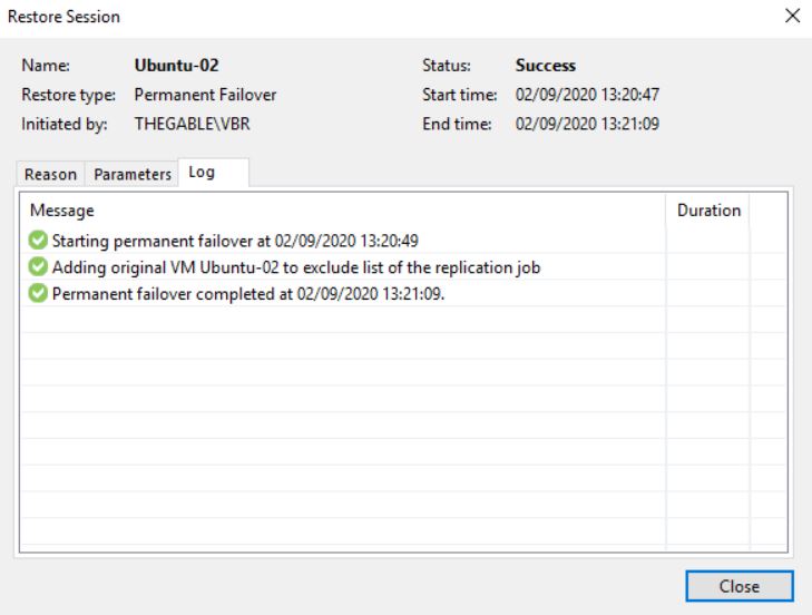
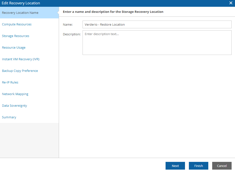
What happens when you complete the task with the Permanent failover? (Picture 9/10/11)
 Picture 9
 Picture 10
 Picture 11
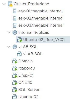
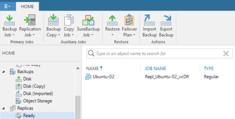
First of all, comparing picture 3 with 12 it is possible to see that one of the Replica Ready VM, and precisely the VM in permanent failover, has been deleted.
 Picture 12
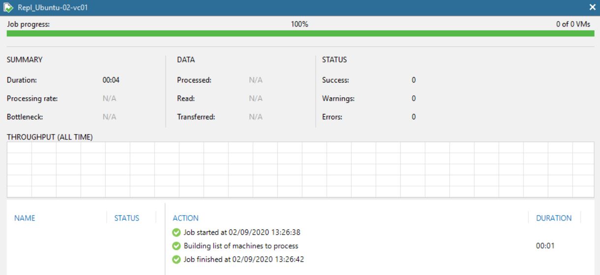
Picture 13 shows that now the replica job contains 0 objects. The right behavior is confirmed by pictures 14,15,16 and 17 where it is shown that the replica is not available anymore.
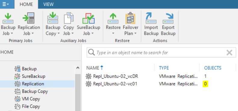 Picture 13
 Picture 14
 Picture 15
 Picture 16
 Picture 17
The cloning job option didn’t change the correct behavior (Pictures 18 and 19)
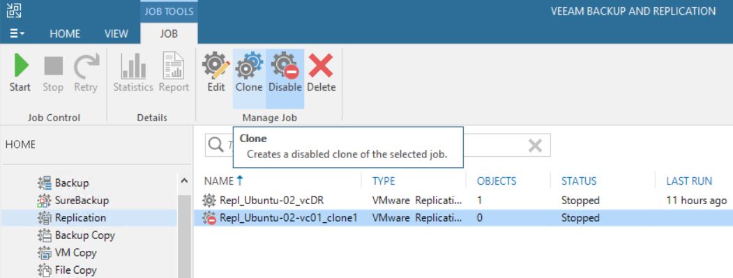 Picture 18
 Picture 19
Let’s sum up. Following the right procedure, the Failover works as aspected
Now …. why the VM has been deleted? The next article will explain it in detail.
 Picture 1
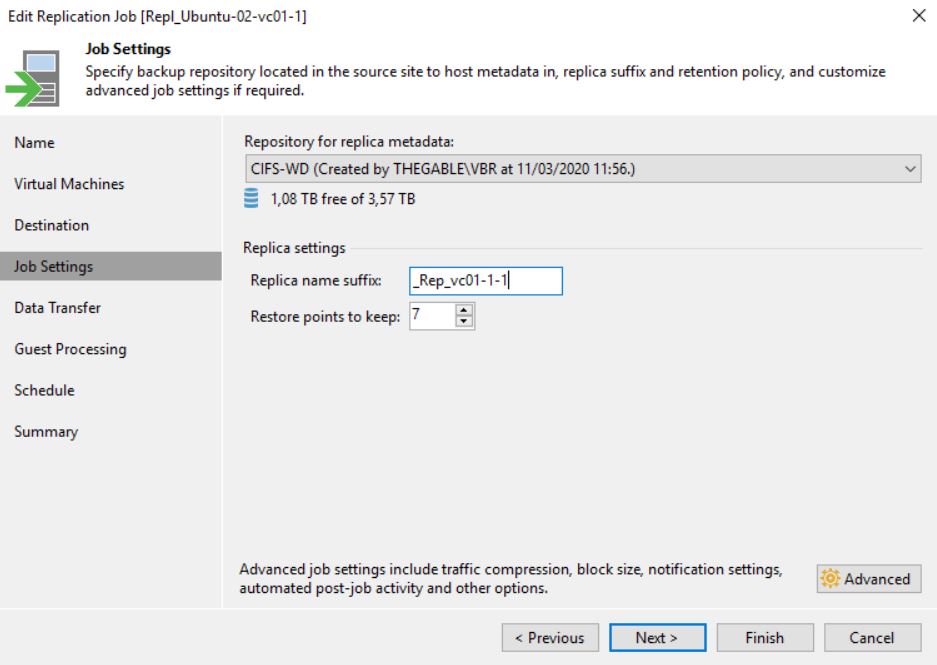 Picture 2
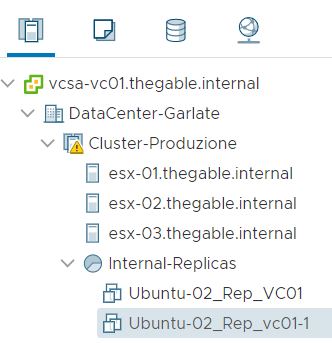 Picture 3
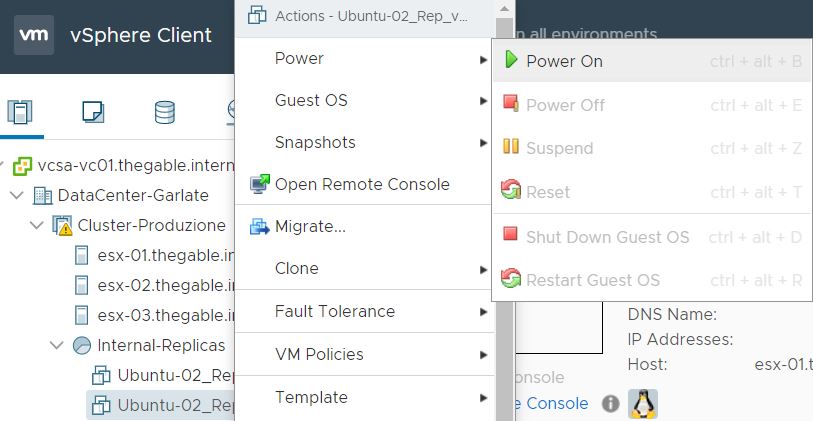 Picture 4
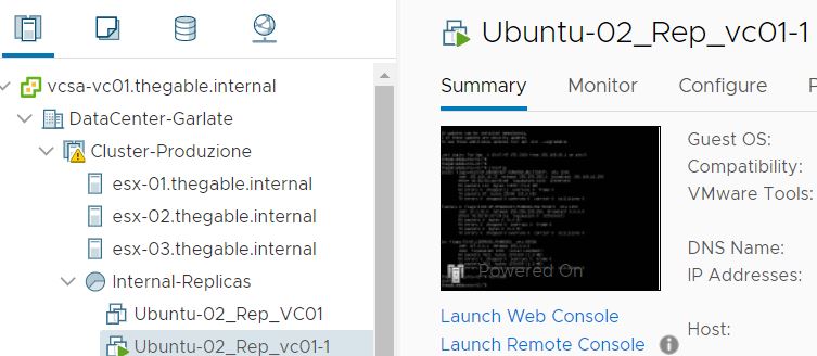 Picture 5
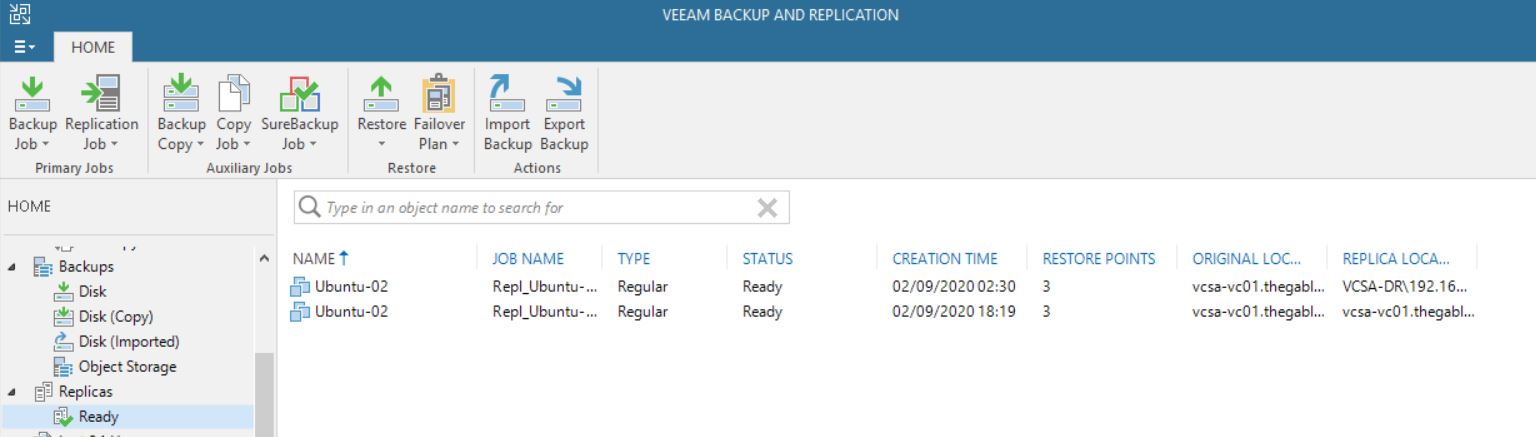 Picture 6
 Picture 7
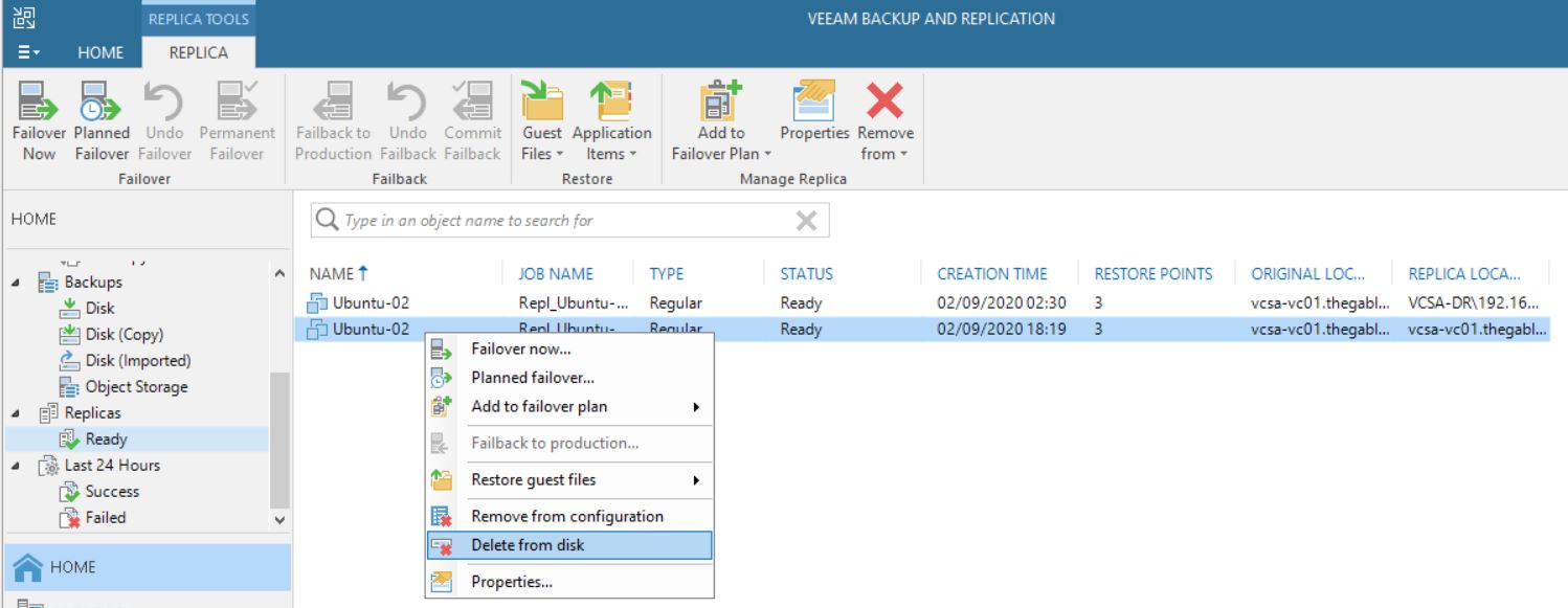 Picture 8
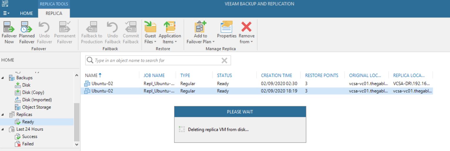 Picture 9
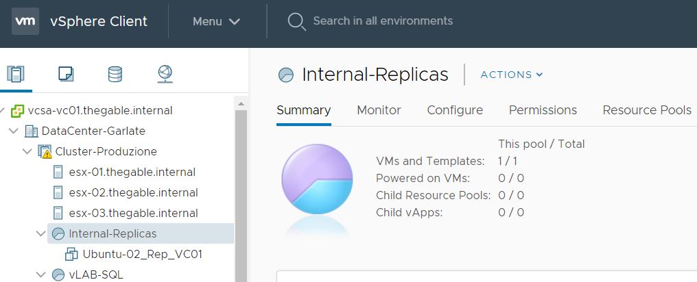 Picture 10
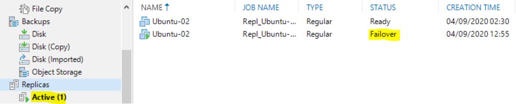 Picture 11
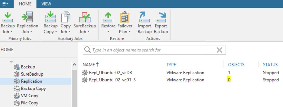 Picture 12
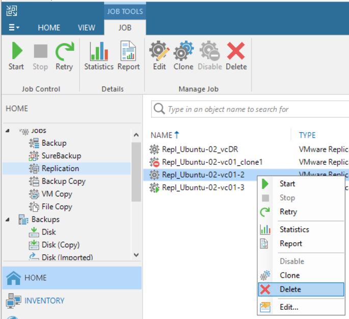 Picture 13
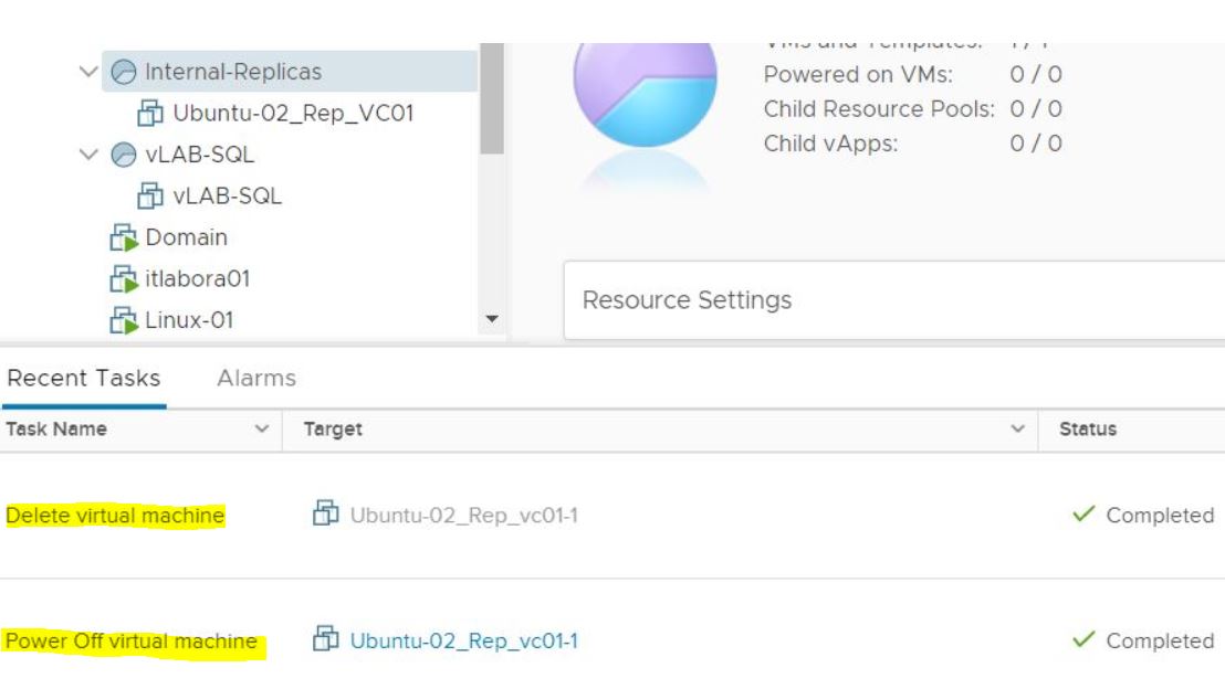 Picture 14
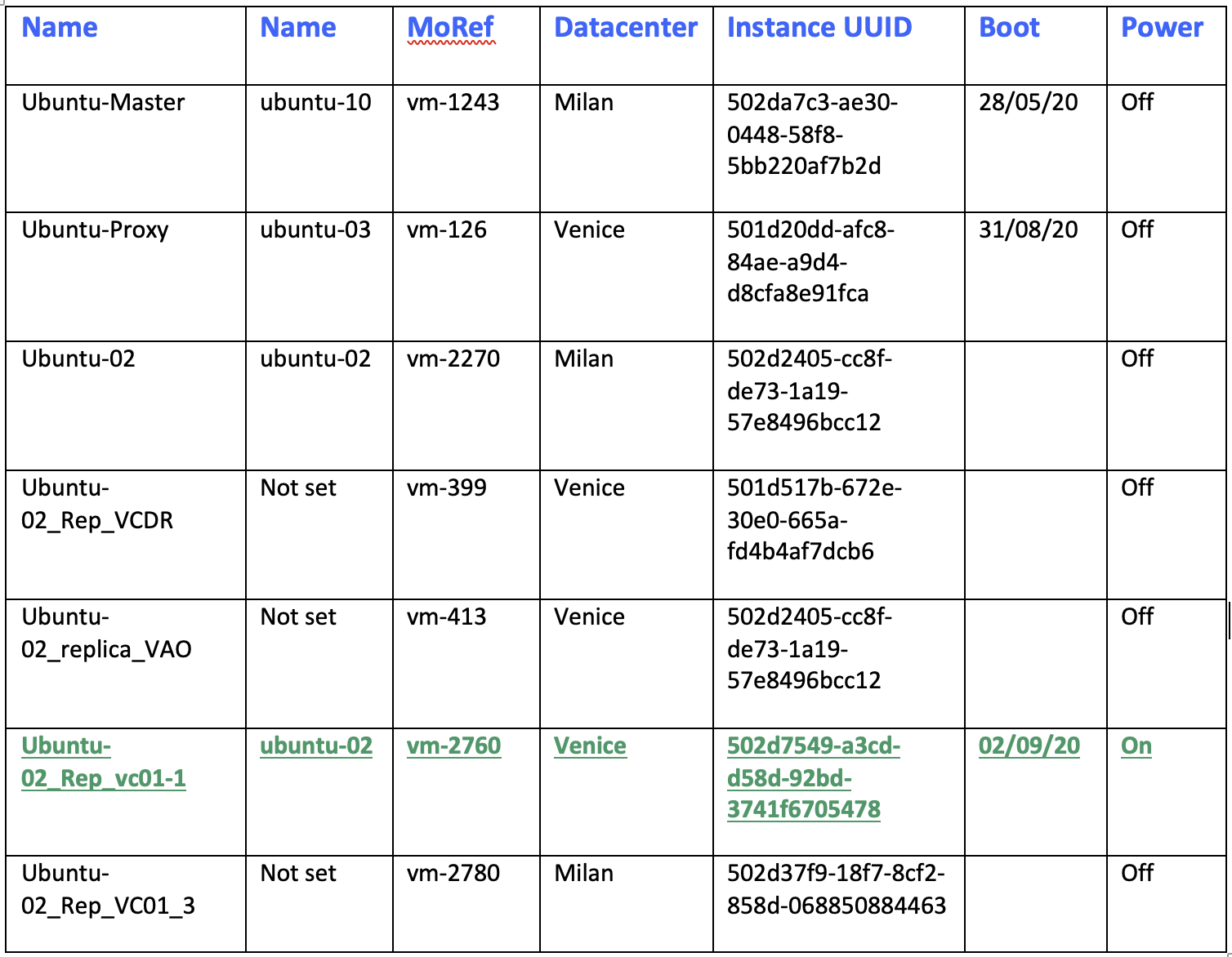 Table 1
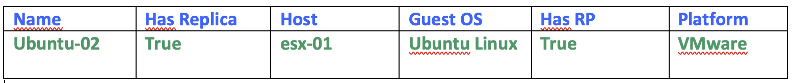 Table2

 Picture 1
 Picture 2
 Picture 3
 Picture 4
 Picture 5
 Picture 6
 (Picture 7)
 Picture 8
 Picture 9
 Picture 10
 Picture 11
 (Picture 12)
 (Picture 13)
 (Picture 14)
 (Picture 15)
 Picture 16
 Picture 1
 Picture 4
 Picture 1
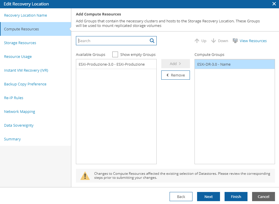 Picture 2
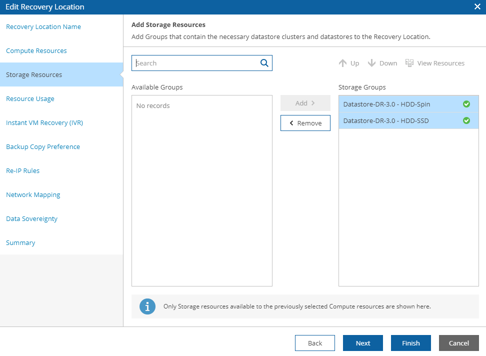 Picture 3
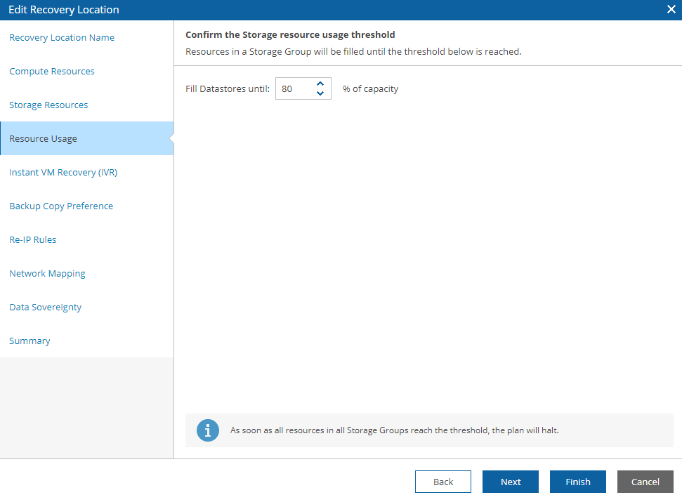 Picture 4
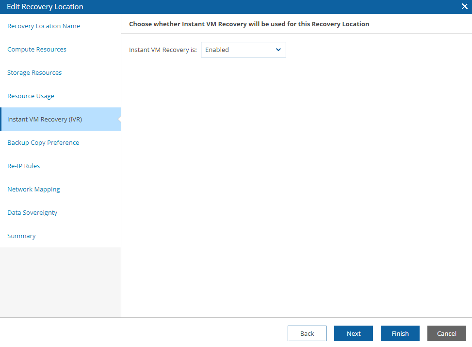 Picture 5
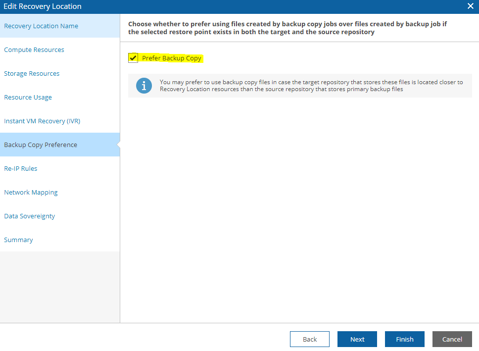 Picture 6
 Picture 7
 Picture 8
 Picture 9
 Picture 10
 Picture 11
 Picture 12
 Picture 13
 Picture 14
 Picture 15
 Picture 16