
Nei precedenti articoli abbiamo visto alcuni dettagli di come è costruita l’architettura di Kubernetes.
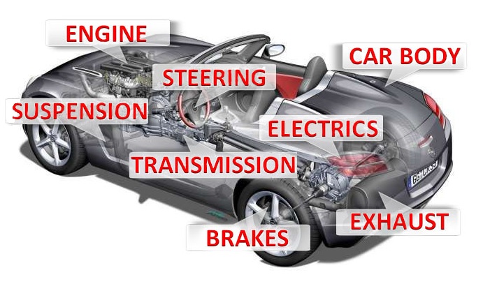
Oggi verranno descritti i meccanismi di funzionamento del motore kubernetes indicando il nome di ogni componente; per rimanere fedeli al paragone del motore dell’autovettura, parleremo degli alberi a camme, valvole, bronzine, … che afferiscono al Cloud Native
Nota1: Non verrà trattata l’installazione di k8s in Datacenter, Cloud e Laboratorio, la rete ha già messo a disposizione esaustivi tutorial.
Per i familiarizzare con k8s vi consiglio di utilizzare Minikube (Piattaforma Linux) Docker Desktop (piattaforma Windows & Mac).
Iniziamo!
Kubernetes Master: E’ il nodo principale del cluster sul quale girano tre processi vitali per l’esistenza del cluster.
- kube-apiserver
- kube-controller-manager
- kube-scheduler
Nel master node è inoltre presente il DataBase etcd, che memorizza tutte le configurazioni create nel cluster.
I nodi che si fanno carico di far girare le applicazioni e quindi i servizi sono detti worker node. I processi presenti sui worker node sono:
- Kubelet
- kube-proxy
kubelet :Un agente che è eseguito su ogni nodo del cluster. Si assicura che i container siano eseguiti in un pod.
Kube-Proxy: Ha la responsabilità di gestire il networking, dalle regole di Routing a quelle di di Load Balancing.
Nota 2: K8s cercherà di utilizzare tutte le librerie disponibili a livello di sistema operativo.
kubectl: E’ Il client ufficiale di Kubernetes (CLI) attraverso il quale è possibile gestire il cluster (Kube-apiserver) utilizzando le API.
Alcuni semplici esempi di comandi kubectl sono:
- kubectl version (indica la versione di k8s installata)
- kubectl get nodes (scopre il numero di nodi del cluster)
- kubectl describe nodes nodes-1 (mostra lo stato di salute del nodo, la piattafoma sulla quale k8s sta girando (Google, AWS, ….) e le risorse assegnate (CPU,RAM)).
Container Runtime: E’ la base sulla quale poggia la tecnologia k8s.
kubernetes supporta diverse runtime tra le quali ricordiamo, container-d, cri-o, rktlet.
Nota 3: La runtime Docker è stata deprecata a favore di quelle che utilizzano le interfacce CRI; le immagini Docker continueranno comunque a funzionare nel cluster.
Gli oggetti base di Kubernetes sono:
- Pod
- Servizi
- Volumi
- Namespace
I controller forniscono funzionalità aggiuntive e sono:
- ReplicaSet
- Deployment
- StatefulSet
- DaemonSet
- Job
Tra i Deployment è indispensabile menzionare Kube-DNS che fornisce i servizi di risoluzione dei nomi. Dalla versione kubernetes 1.2 la denominazione è cambiata in Core-dns.
Add-On: servono a configurare ulteriori funzionalità del cluster e sono collocati all’interno del name space kube-system (come Kube-Proxy, Kube-DNS, kube-Dashboard)
Gli Add-on sono categorizzati in base al loro utilizzo:
- Add-on di Netwok policy. (Ad esempio l’add-on NSX-T si preoccupa della comunicazione tra l’ambiente K8s e VMware)
- Add-on Infrastrutturali (Ad esempio KubeVirt che consente la connessione con le architetture virtuali)
- Add-on di Visualizzazione e Controllo (Ad esempio Dashboard un’interfaccia web per K8s).
Per la messa in esercizio, gli Add-on utilizzano i controller DaemonSet e Deployment.
L’immagine di figura 1 riepiloga quanto appena esposto.
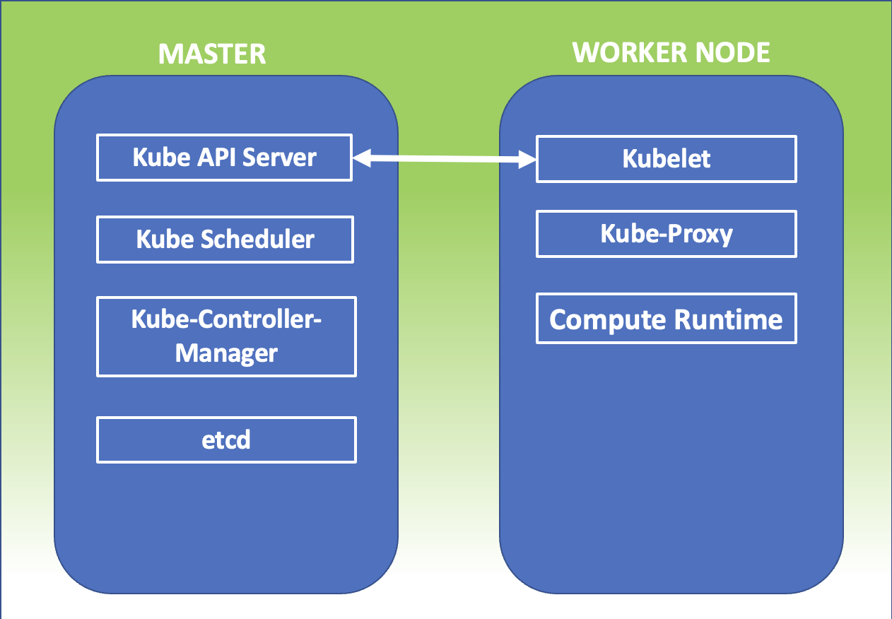 Figura 1

 Figura 1
 Figura 2
 Figura 3
 Immagine 1
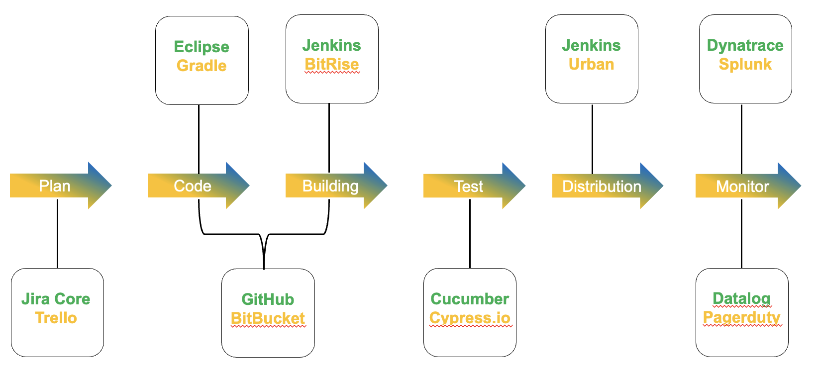 Immagine 2
 Picture 1
 Picture 2
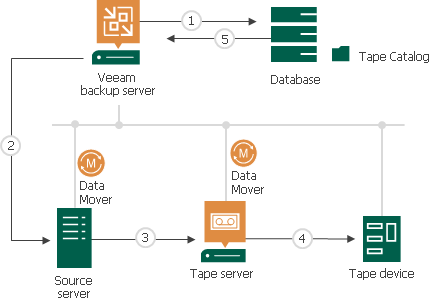
 Picture 1
 Picture 2
 Picture 3
 Picture 4
 Picture 5
 Picture 1
 Picture 2
 Picture 3
 Picture 4
 Picture 5
 Picture 6