Oggi illustreremo come indicare al Veeam Disaster Recovery Orchestrator quali risorse utilizzare per avviare un piano di Disaster Recovery.
Prima di leggere il presente articolo, vi suggeriamo di leggere l’articolo precedente (cliccando qui) che vi permette di verificare lo stato del Server VDrO.
Lo strumento principe dell’etichettatura delle risorse è Veeam One che ricordiamo viene di default installato contestualmente con il Veeam Disaster Recovery Orchestrator v.5.
La procedura è molto semplice:
Dopo essersi collegati via RDP al VDrO Server selezionate sul desktop la voce Veeam One Client (Vedi figura 1)
Figura 1
Dopo aver selezionato la voce Business View (in basso a sinistra), le risorse da etichettare sono:
I Cluster: attraverso tale voce sono identificate le risorse vCenter di Disaster Recovery e di produzione (Figura 2)
I DataStores: attraverso tale voce sono identificate le aree disco ove risiederanno le VM una volta accese (Figura 3)
Le Virtual Machines: attraverso tale voce sono identificate le VM che garantiscono la continuità di servizio in caso di Disastro (Figura 4 e 5).
Figura 2
Figura 3
Figura 4
Figura 5
Nota 1: I job di replica sono stati configurati sul VBR embedded del server VDrO (vedi figura 6)
Figura 6
Nota 2: L’operazione di etichettatura (tagging) è trattata in un precedente post disponibile al seguente link:
Nei precedenti articoli abbiamo visto alcuni dettagli di come è costruita l’architettura di Kubernetes.
Oggi verranno descritti i meccanismi di funzionamento del motore kubernetes indicando il nome di ogni componente; per rimanere fedeli al paragone del motore dell’autovettura, parleremo degli alberi acamme, valvole, bronzine, … che afferiscono al Cloud Native
Nota1: Non verrà trattata l’installazione di k8s in Datacenter, Cloud e Laboratorio, la rete ha già messo a disposizione esaustivi tutorial.
Per i familiarizzare con k8s vi consiglio di utilizzare Minikube (Piattaforma Linux) Docker Desktop (piattaforma Windows & Mac).
Iniziamo!
Kubernetes Master: E’ il nodo principale del cluster sul quale girano tre processi vitali per l’esistenza del cluster.
kube-apiserver
kube-controller-manager
kube-scheduler
Nel master node è inoltre presente il DataBaseetcd, che memorizza tutte le configurazioni create nel cluster.
I nodi che si fanno carico di far girare le applicazioni e quindi i servizi sono detti worker node. I processi presenti sui worker node sono:
Kubelet
kube-proxy
kubelet :Un agente che è eseguito su ogni nodo del cluster. Si assicura che i container siano eseguiti in un pod.
Kube-Proxy: Ha la responsabilità di gestire il networking, dalle regole di Routing a quelle di di Load Balancing.
Nota 2: K8s cercherà di utilizzare tutte le librerie disponibili a livello di sistema operativo.
kubectl: E’ Il client ufficiale di Kubernetes (CLI) attraverso il quale è possibile gestire il cluster (Kube-apiserver) utilizzando le API.
Alcuni semplici esempi di comandi kubectl sono:
kubectl version (indica la versione di k8s installata)
kubectl get nodes (scopre il numero di nodi del cluster)
kubectl describe nodes nodes-1 (mostra lo stato di salute del nodo, la piattafoma sulla quale k8s sta girando (Google, AWS, ….) e le risorse assegnate (CPU,RAM)).
Container Runtime: E’ la base sulla quale poggia la tecnologia k8s.
kubernetes supporta diverse runtime tra le quali ricordiamo, container-d,cri-o, rktlet.
Nota 3: La runtime Docker è stata deprecata a favore di quelle che utilizzano le interfacce CRI; le immagini Docker continueranno comunque a funzionare nel cluster.
Gli oggetti base di Kubernetes sono:
Pod
Servizi
Volumi
Namespace
I controllerforniscono funzionalità aggiuntive e sono:
ReplicaSet
Deployment
StatefulSet
DaemonSet
Job
Tra iDeployment è indispensabile menzionare Kube-DNSche fornisce i servizi di risoluzione dei nomi. Dalla versione kubernetes 1.2 la denominazione è cambiata in Core-dns.
Add-On: servono a configurare ulteriori funzionalità del cluster e sono collocati all’interno del name space kube-system (come Kube-Proxy, Kube-DNS, kube-Dashboard)
Gli Add-on sono categorizzati in base al loro utilizzo:
Add-on di Netwok policy. (Ad esempio l’add-on NSX-T si preoccupa della comunicazione tra l’ambiente K8s e VMware)
Add-on Infrastrutturali(Ad esempio KubeVirt che consente la connessione con le architetture virtuali)
Add-on di Visualizzazione e Controllo (Ad esempio Dashboard un’interfaccia web per K8s).
Per la messa in esercizio, gli Add-on utilizzano i controller DaemonSet e Deployment.
L’immagine di figura 1 riepiloga quanto appena esposto.
Una buona modalità per descrivere gli ambient cloud-native è rifarsi all’immagine della vostra autovettura.
Il container è il motore, k8s è la centrale elettronica che gestisce il buon funzionamento del mezzo, i conducenti, indicando il percorso e la meta, selezionano il tipo di servizio che dovrà essere erogato.
L’articolo di oggi vi svelerà alcuni dettagli di architettura per comprendere come “l’automobile” riesce a giungere la destinazione in modalità efficente.
I Container sono di due tipologie:
Il primo è detto System Container. E’ la carrozzeria dell’autovettura (intendo dalle lamiere a sedili, volante, leva del cambio e accessori).
Spesso per semplicità di creazione è una Virtual Machine (VM) con sistema operativo Linux (può essere anche Windows).
I servizi più comuni presenti nella VM sono ssh, cron e syslog, il File System è di tipo ext3, ext4, ecc.
La seconda tipologia è detta ApplicationContainer ed è il luogo dove l’immagine realizzerà le attività.
Nota1: L’immagine non è un singolo e grosso file. Di norma sono più file che attraverso un sistema interno di puntamento incrociato permettono all’applicazione di operare nel modo corretto.
L’application Container (d’ora in avanti solo container), ha una modalità di funzionamento basata su una rigida logica, dove tutti livelli (layers) hanno la peculiartità di comunicare tra loro e sono interdipendenti.
Figura 1
Questo approccio è molto utile poiché è in grado di gestire i cambiamenti che possono avvenire nel corso del tempo in modalità efficace perchè gerarchica.
Facciamo un esempio: Nel momento in cui avviene un cambio di configurazione del servizio, per il quale viene aggiornato il Layer C, il Layer A e B non ne sono impattati, il che significa che NON devono essere a loro volta modificati.
Visto i Developer hanno piacere nell’affinare le proprie immagini (program file) piuttosto che le dipendenze, ha senso impostare la logica di servizion nella modalità indicata in figura 2 dove le dipendenze non sono impattate da una nuova immagine.
Figura 2
Nota2 : Il File system sul quale si appoggiano le immagini (nell’esempio del motore dell’auto parliamo di pistoni, bielle, alberi …) è principalmente di tre differenti tipologie:
Overlay
Overlay 2
AUFS
Nota3: Un buon consiglio lato sicurezza è quello do non costruire l’architettura in modo che le password siano contenute nelle immagini (Baked in – Cucinata)
Una delle splendide novità introdotte nel mondo containers è la gestione delle immagini:
In un ambiente classico di alta affidabilità, l’applicazione viene installata su ogni singolo nodo del cluster.
Nei container, l’applicazione viene scaricata e distribuita solo quando il carico di lavoro richiede maggiori risorse, quindi un nuovo nodo del cluster con una nuova immagine.
Per questo motivo le immagini sono salvate all’interno di magazzini “virtuali”, che possono essere locali oppure distribuiti su internet. Sono chiamati “Register Server”.
I più famosi sono Docker Hub, Google Container Registry, Amazon Elastic Container Registry, Azure Container Registry.
Concludiamo il presente articolo parlando di gestione delle risorse associate ad un servizio.
La piattaforma container utilizza due funzionalità denominate Cgroup e NameSpace per assegnare le risorse che lavorano a livello di kernel.
Lo scopo del Cgroup è di assegnare allo specifico processo (PID) le corrette risorse (CPU&RAM).
I Name space hanno lo scopo di ragguppare i differenti processi e fare in modo che siano isolati tra loro (Multitenancy).
La tipologia di NameSpace puo interesare tutti i componenti del servizio come indicato nella lista qui sotto.
Cgroup
PID
Users
Mount
Network
IPC (Interprocess communication)
UTS (consente a un singolo sistema di apparire con nomi di host e domini diversi e con processi diversi, utile nel caso di migrazione)
Un esempio di limitare le risorse di un’applicazione è indicata nella figura 3 dove l’immagine thegable, scaricata dal Register Server grcgp,ha un limite di risorse RAM e CPU assegnate.
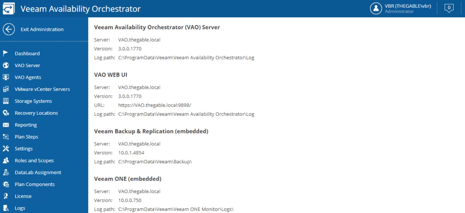
Before proceeding please check that the VAO current version on the server is 3.0 (picture 1).
Picture 1
After downloading the ISO file from the Veeam website and mounting it (picture 2)
Picture 2
just select the “Setup” voice; the wizard immediately begins the upgrade (picture 3).
Picture 3
Please check that the previous version of VAO has been discovered. If so the upgrade button is available (picture 4).
Picture 4
The setup checks if Visual C++ 2019 Redistributable package is already installed. If not it will automatically be deployed. This procedure requires the server reboot (pictures 5 and 6).
Picture 5
Picture 6
After reboot is completed, relaunch the setup. The wizard will show which components will be automatically upgraded (picture 7).
picture 7
Now the wizard will ask for a valid license (picture 8) and will install the missing components (Pictures 9 and 10).
Picture 8
picture 9
picture 10
The next steps are about the Veeam Databases.
The wizard will ask to connect to them and update the VBR one if necessary (pictures 11 and 12).
Picture 11
Picture 12
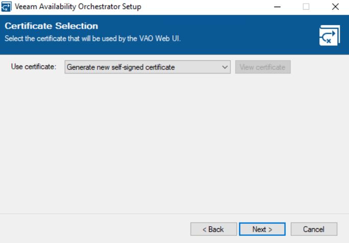
The main point of the upgrade procedure is the certification step.
As shown in picture 13, the wizard will ask the VAO administrator which certificate to use. It can be a self-signed and autogenerated or an own certificate created from an external authority.
My suggestion is to ask your security specialist to know which is the best choice for your company.
Picture 13
Picture 14
Clicking on the install button it will complete the upgrade wizard as shown in pictures 15 & 16.
Picture 15
Picture 16
After upgrading please check the versions of VAO (4.0.0.2088), VBR (11.0.0.837), ONE (11.0.0.1379) now installed.
Just a note before ending the article: has already said, VAO (Veeam Availability Orchestrator) has changed its name to VDrO (Veeam Disaster Recovery Orchestrator).
The web pages of the product still show the old name. It will be updated in the next release.
Let’s continue the VDrO features description talking about scope (Picture 1).
Picture 1
The VDrO controls access to its functionality with the scopes.
A scope defines which operations users can perform.
Let’s back to my example, I created a SQL Production scope where only the users belonging to the SQL administrator group can manage and launch the DR process.
The plan components are probably the main VRrO attention point (Picture 2).
(Picture3)
From this menu, it’s possible to group as a single entity all objects you need to create a Disaster Recovery strategy.
I’m talking scope (first to select), VM (applications and services), recovery locations, plan steps, credentials, and jobs template.
To be clearer, it’s like creating a picnic basket and putting it inside different dishes.
Now you just have to lay the table.
How to do it? (Which dishes do I have to put into the basket?)
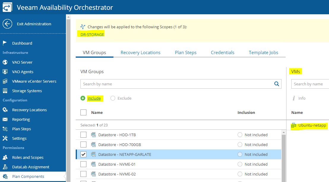
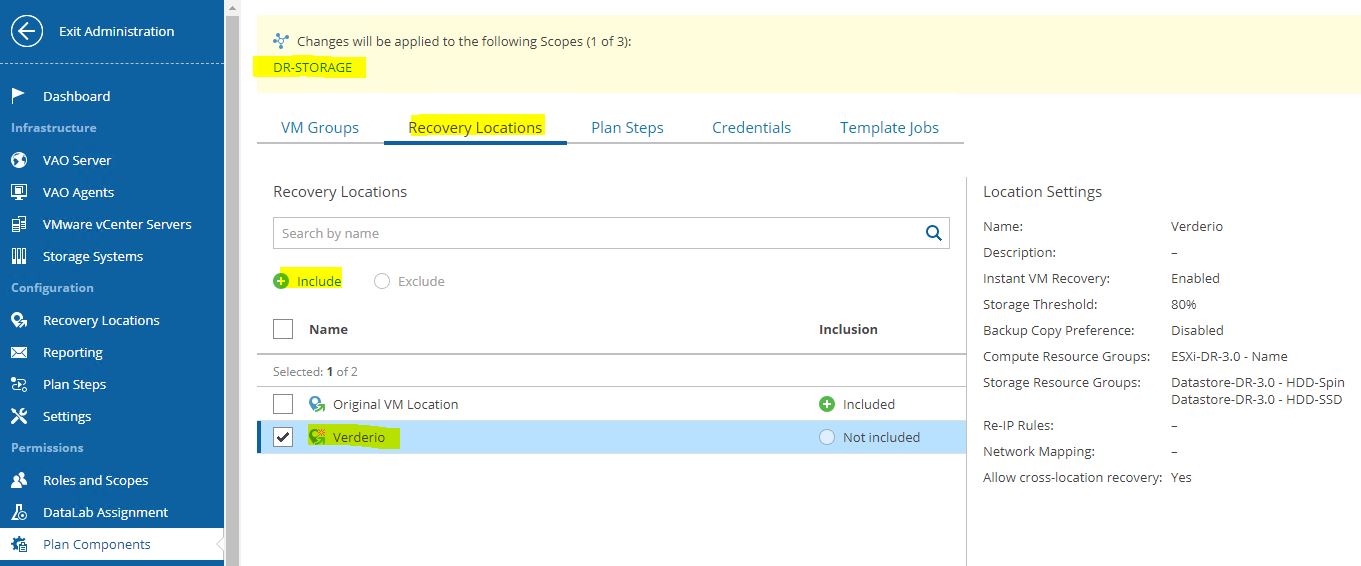
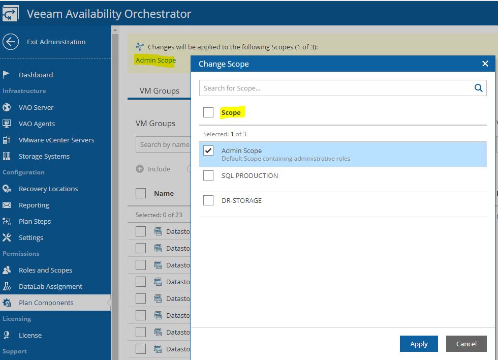
Just select scope (Picture 4), then from VM groups include the needed VMs source (Picture 5), from recovery locations, select the DR site (picture 6), and at the end select plan steps, credential, and Template Job.
Picture 4
Picture 5
Picture 6
The last point is the DataLabs assignment but I’m sure you can now include them on the right scopes.
Exit from the Administrator menu and move to the main menu to create the first Recovery Plan.
The wizard is very easy to be used:
Picture 7
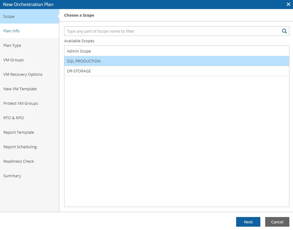
Picture 8 shows how to select the Scope.
Picture 8
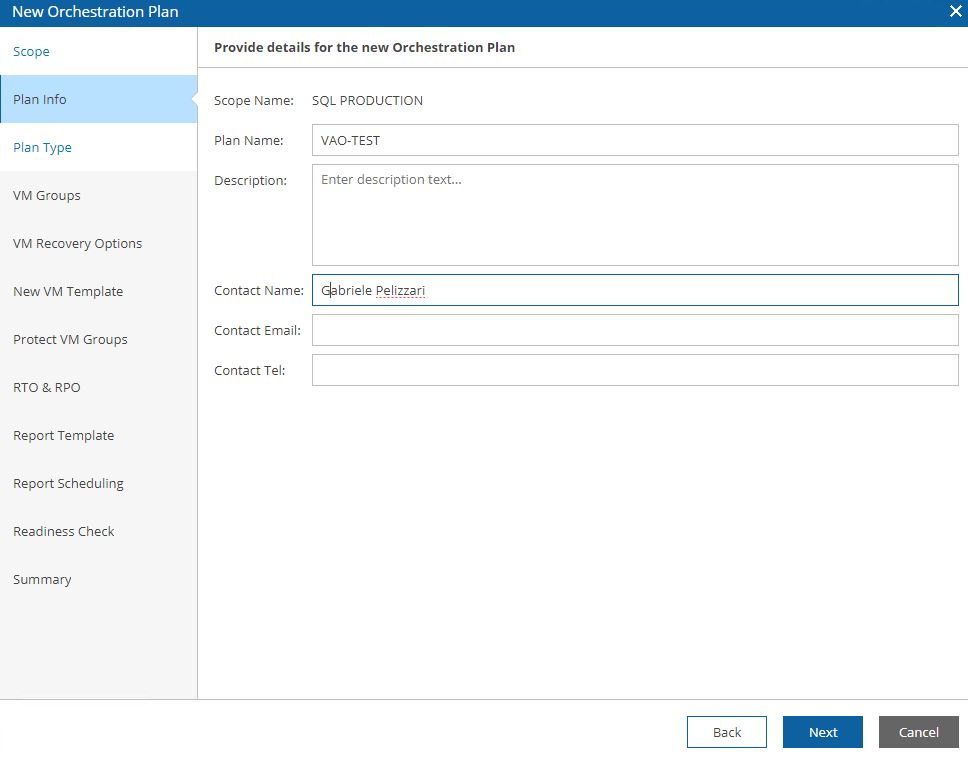
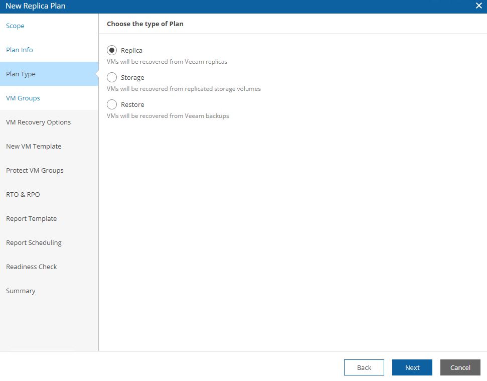
Picture 9 shows the detailed plan info and Picture 10 the plan type (next articles will deep how to set them up).
Picture 9
Picture 10
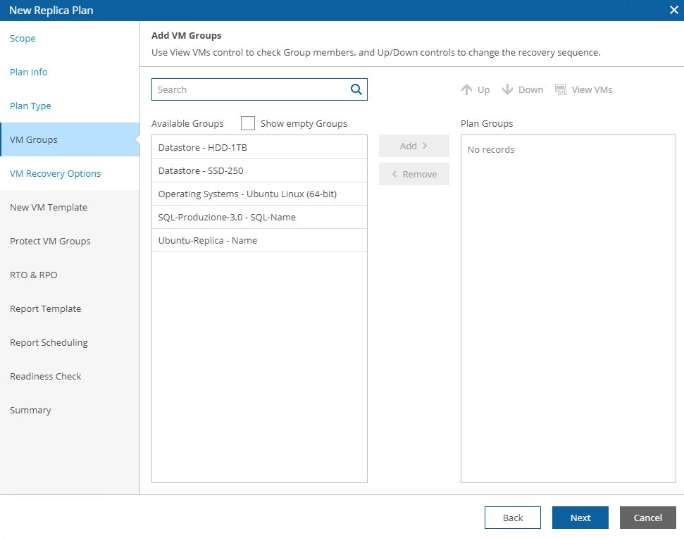
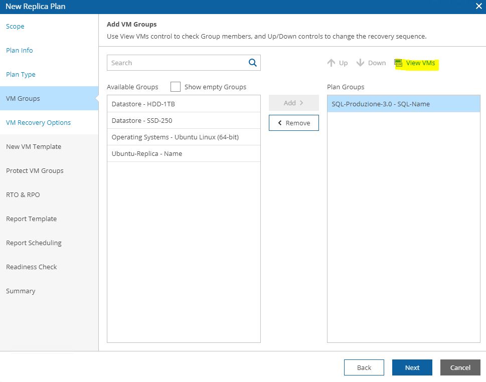
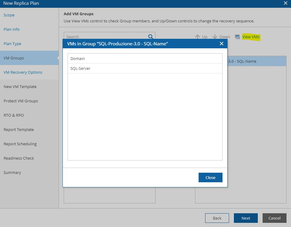
Pictures 11, 12, 13 show how it’s possibles to discover the VMs that belong to the groupselecting VM group.
Picture 11
Picture 12
Picture 13
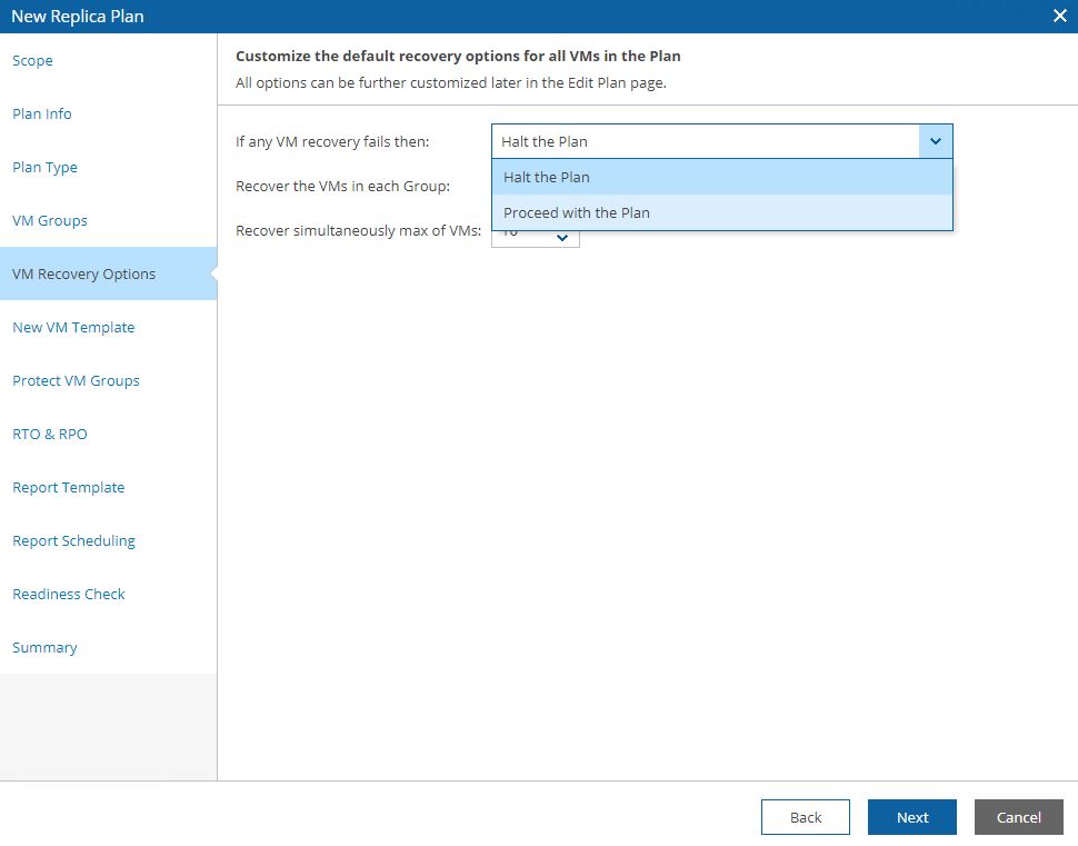
Picture 14 shows the control options for the DR plan. If something goes wrong the plan can be halted or not.
Picture 14
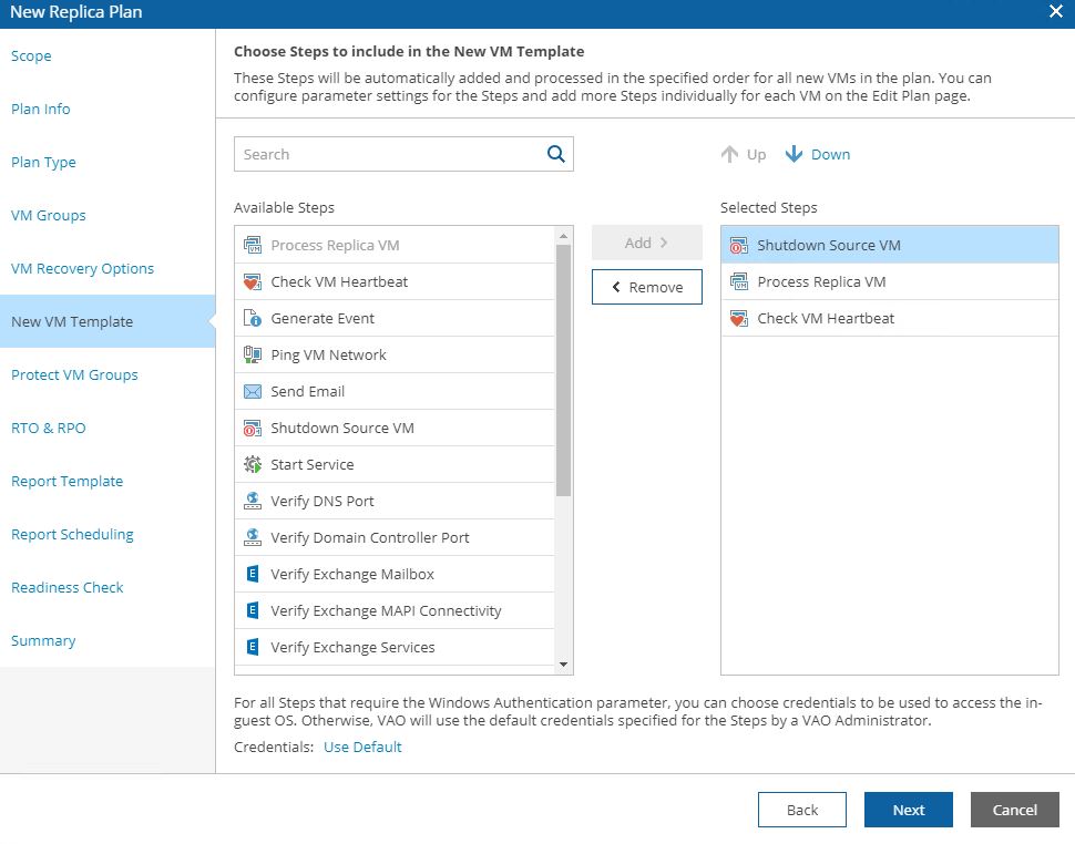
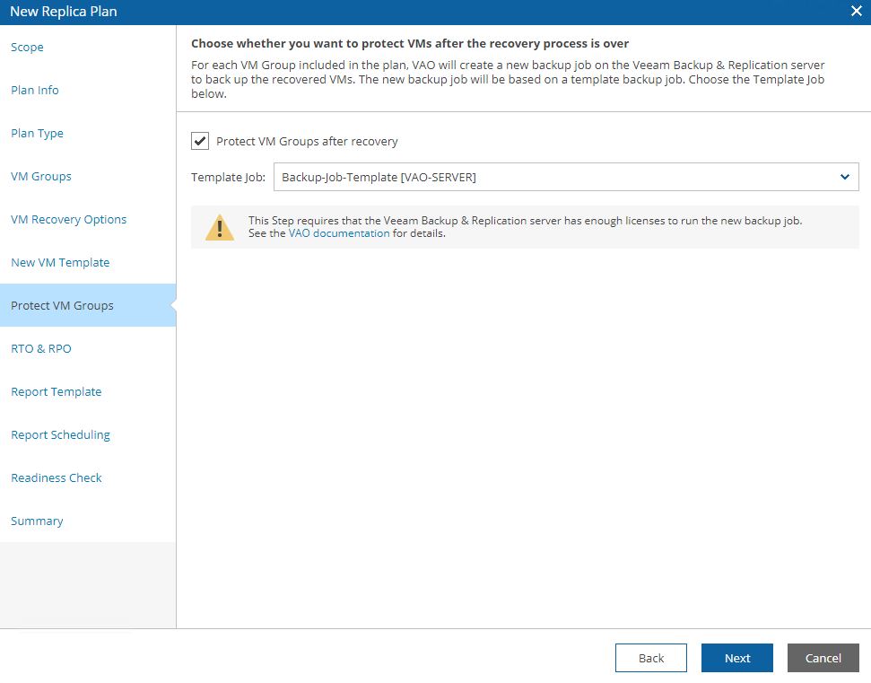
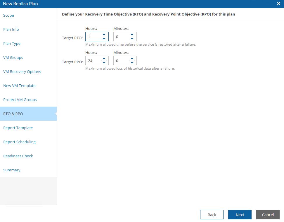
Picture 15 shows the steps, 16 the option to protect VMs switched on after the failover has been completed, 17 the RPO and RTO that the plan has to respect.
Picture 15
Picture 16
Picture 17
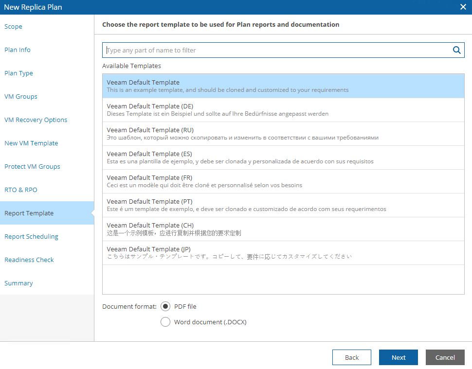
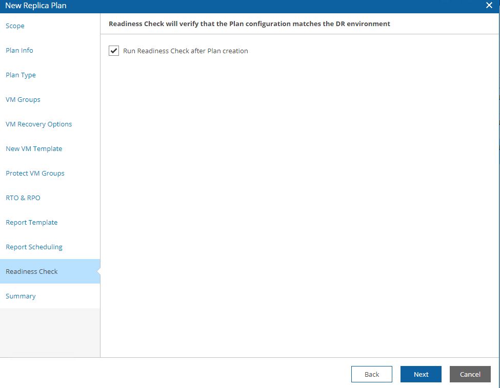
Picture 18 shows the template docs that will be used, while picture 19 shows a (for me)interesting mandatory check option.
Before doing any new activity the Readiness check analyzes that all components are correctly set up.
Picture 18
Picture 19
In my next article, I will cover two examples: DR-plan from Replica and DR-plan from backup. Keep in touch!

 Figura 1
 Figura 2
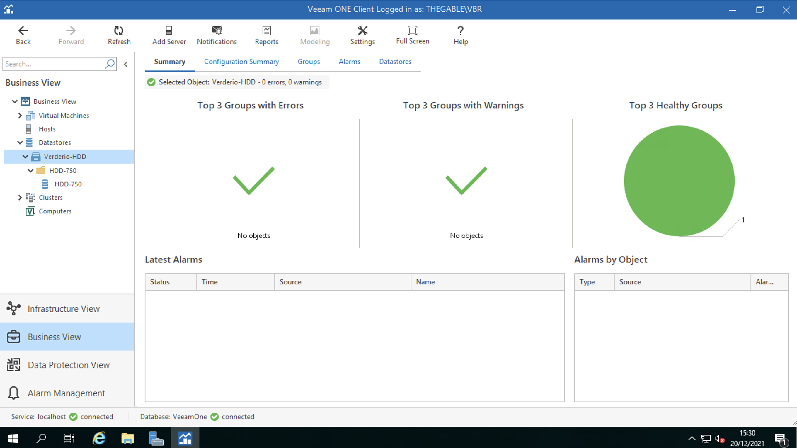 Figura 3
 Figura 4
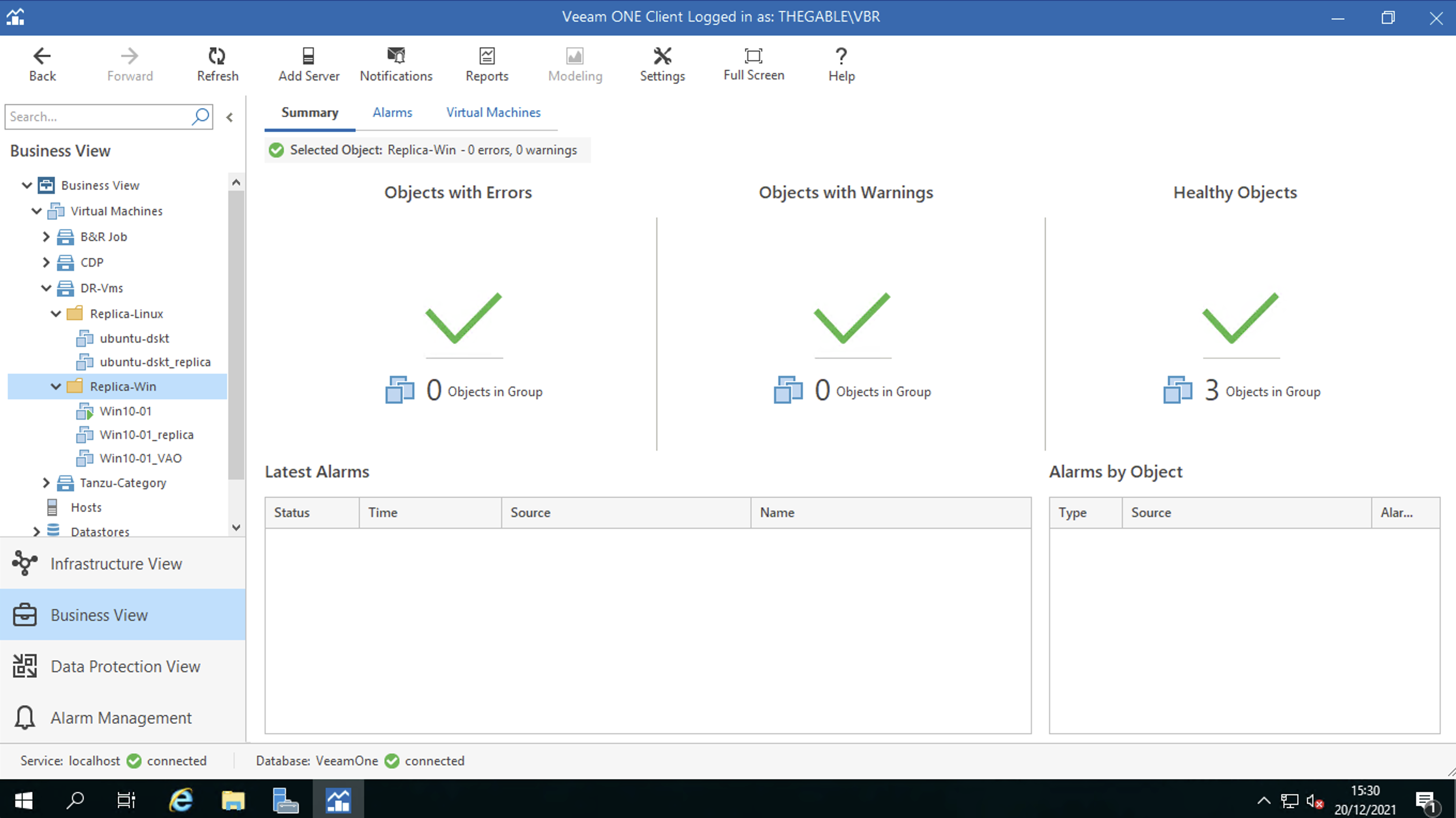 Figura 5
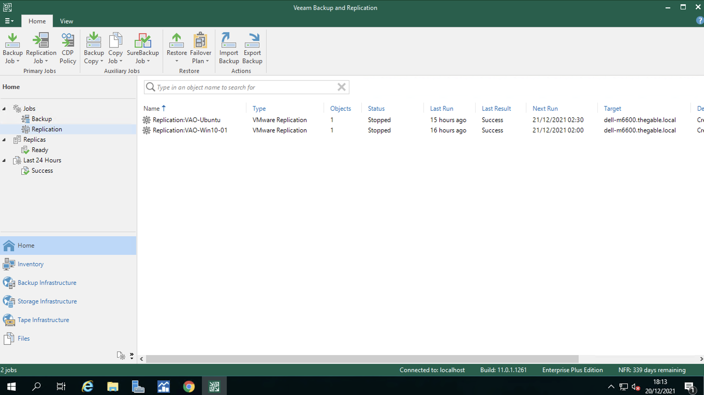 Figura 6
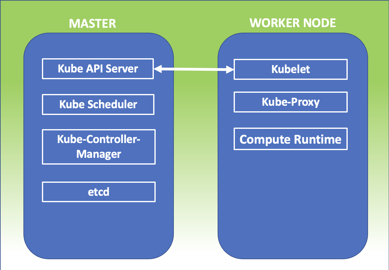 Figura 1
 Figura 1
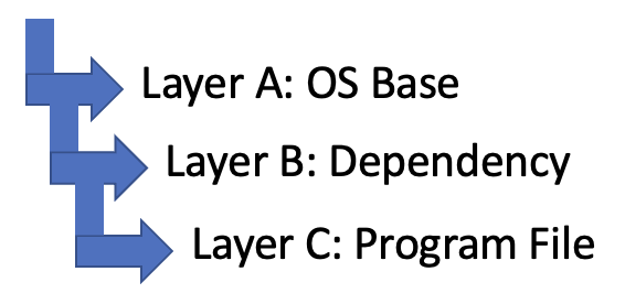 Figura 2
 Figura 3
 Picture 1
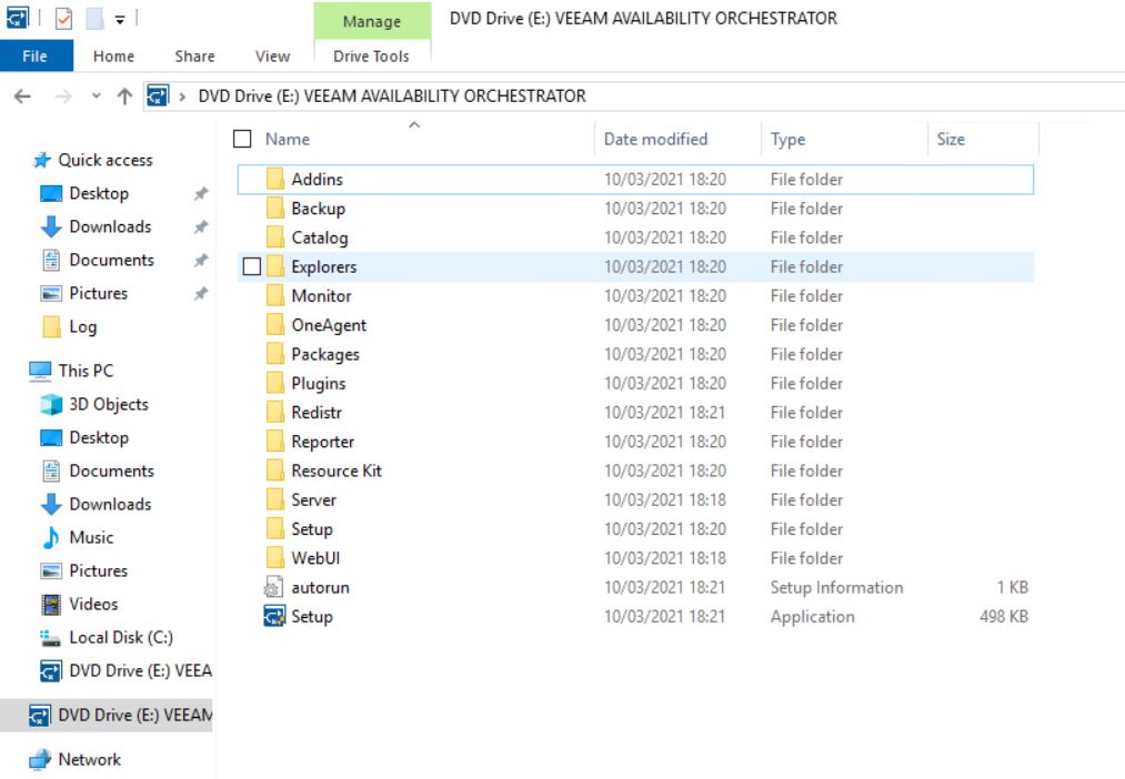 Picture 2
 Picture 3
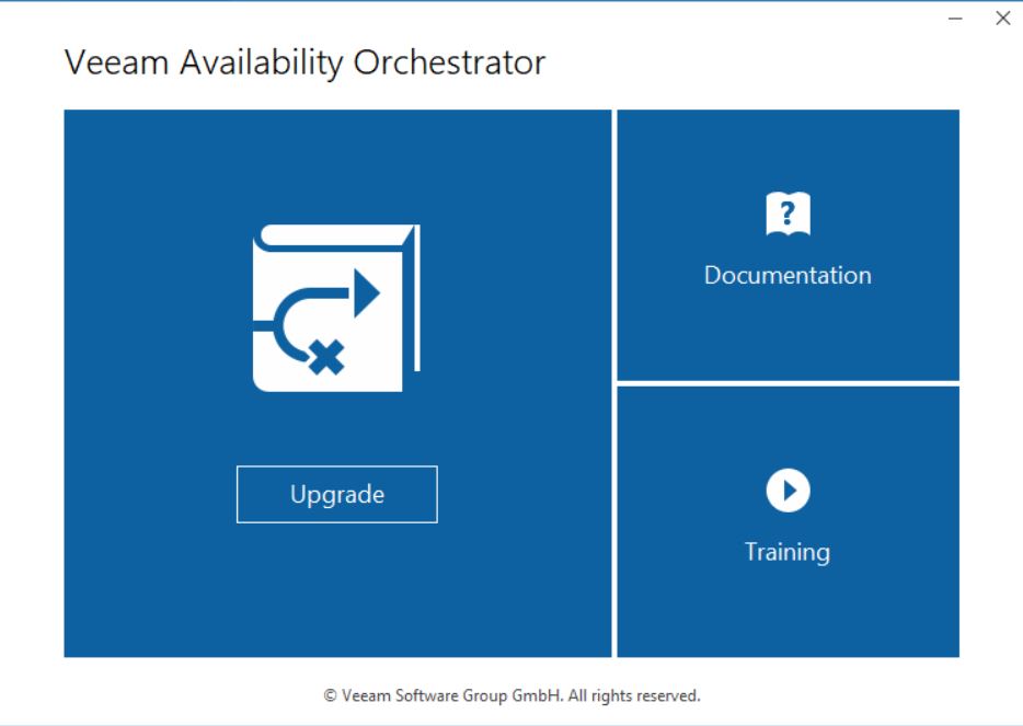 Picture 4
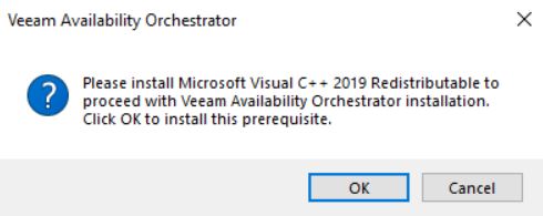 Picture 5
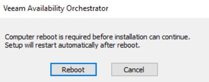 Picture 6
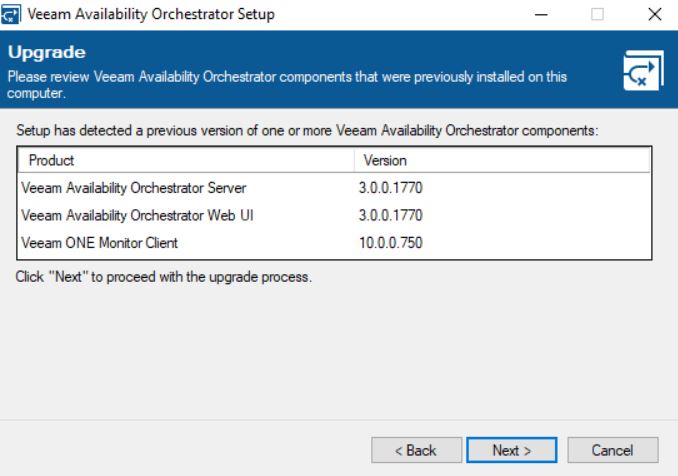 picture 7
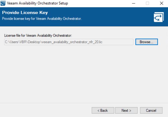 Picture 8
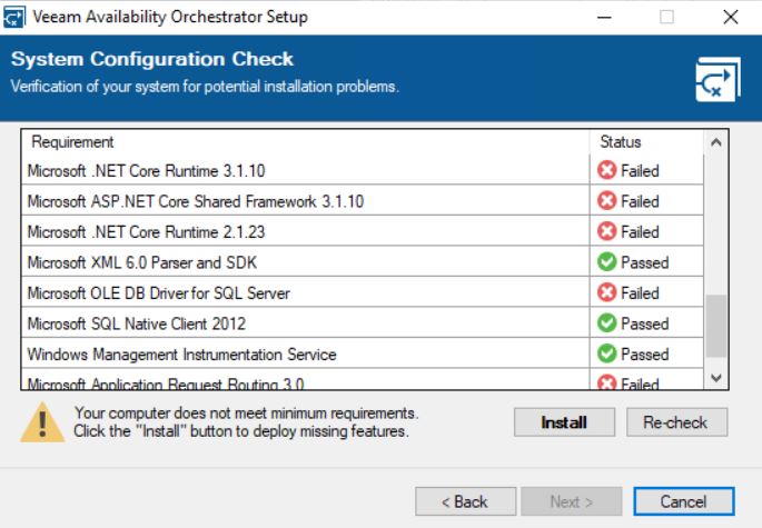 picture 9
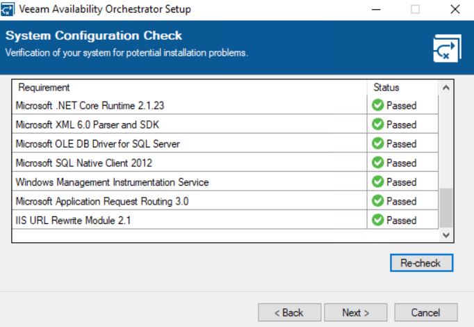 picture 10
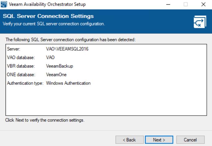 Picture 11
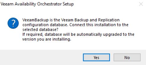
 Picture 13
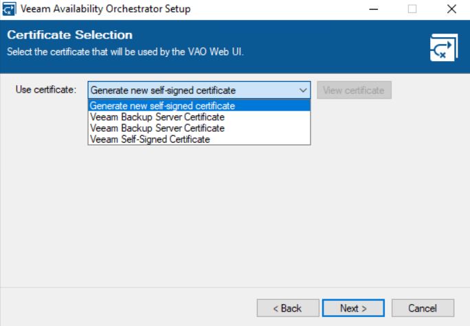 Picture 14
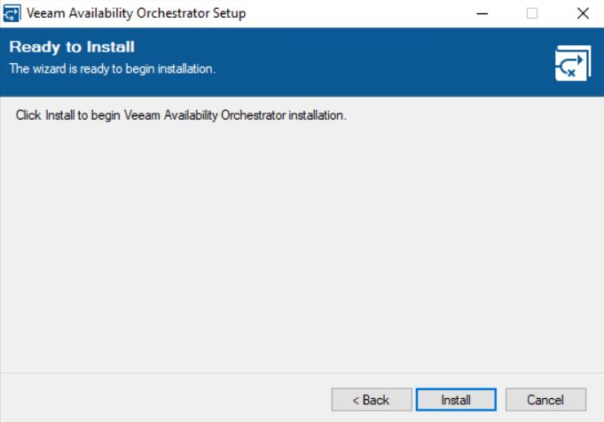 Picture 15
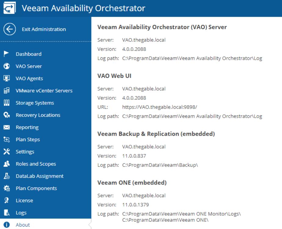 Picture 16
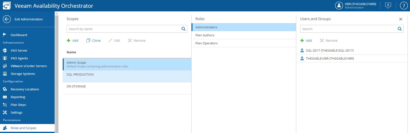 Picture 1
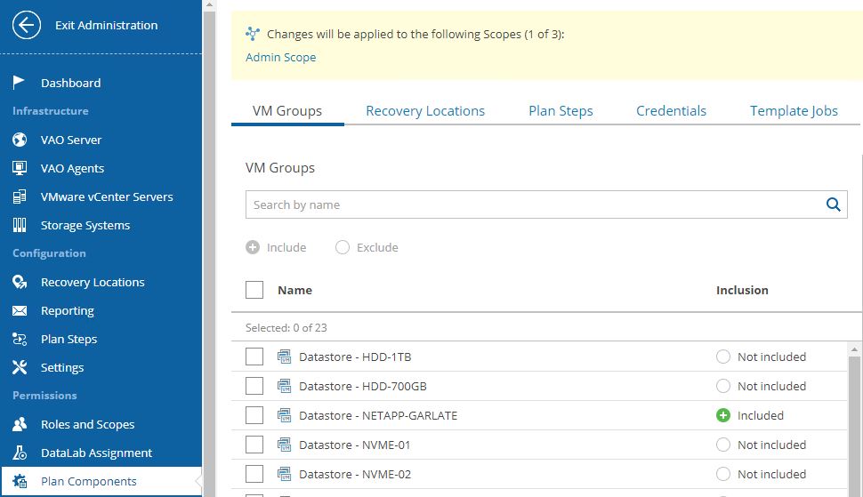
 Picture 4