
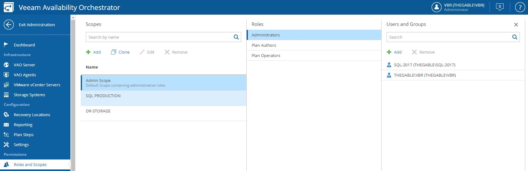
Let’s continue the VDrO features description talking about scope (Picture 1).
 Picture 1
The VDrO controls access to its functionality with the scopes.
A scope defines which operations users can perform.
Let’s back to my example, I created a SQL Production scope where only the users belonging to the SQL administrator group can manage and launch the DR process.
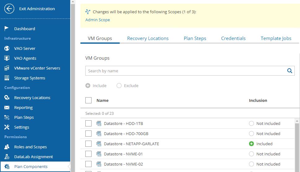
The plan components are probably the main VRrO attention point (Picture 2).
(Picture3)
From this menu, it’s possible to group as a single entity all objects you need to create a Disaster Recovery strategy.
I’m talking scope (first to select), VM (applications and services), recovery locations, plan steps, credentials, and jobs template.
To be clearer, it’s like creating a picnic basket and putting it inside different dishes.
Now you just have to lay the table.
How to do it? (Which dishes do I have to put into the basket?)
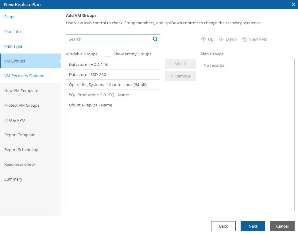
Just select scope (Picture 4), then from VM groups include the needed VMs source (Picture 5), from recovery locations, select the DR site (picture 6), and at the end select plan steps, credential, and Template Job.
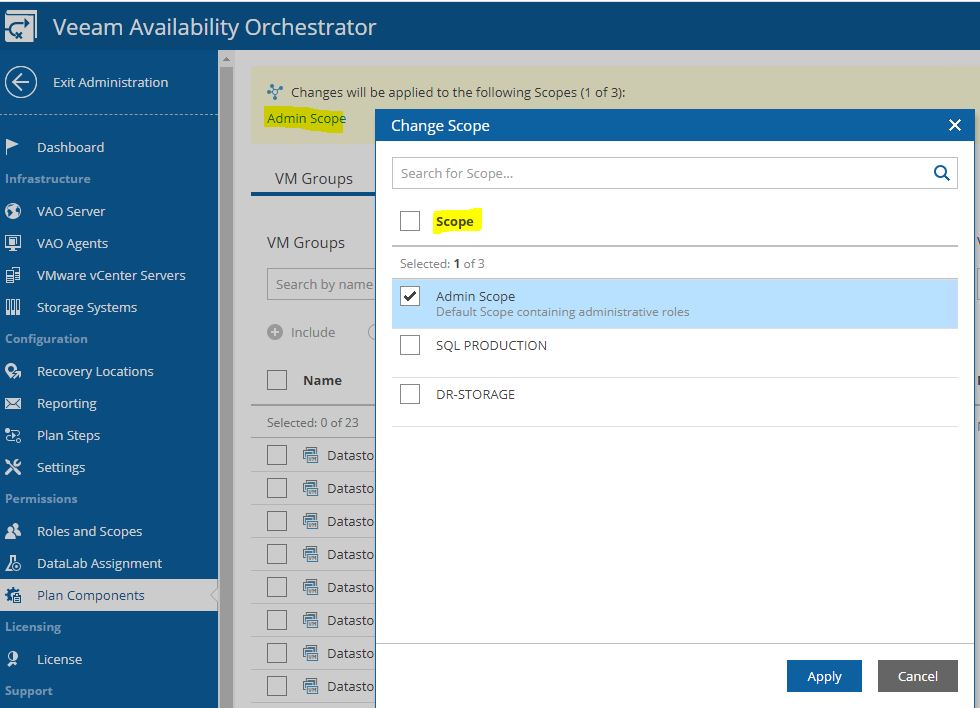 Picture 4
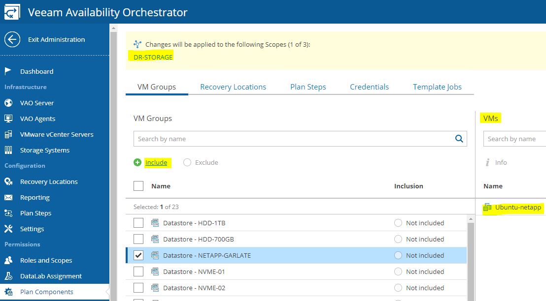 Picture 5
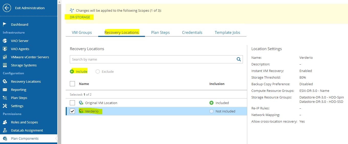
Picture 6
The last point is the DataLabs assignment but I’m sure you can now include them on the right scopes.
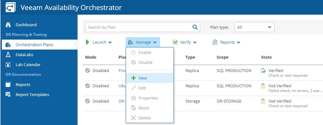
Exit from the Administrator menu and move to the main menu to create the first Recovery Plan.
The wizard is very easy to be used:
Picture 7
Picture 8 shows how to select the Scope.
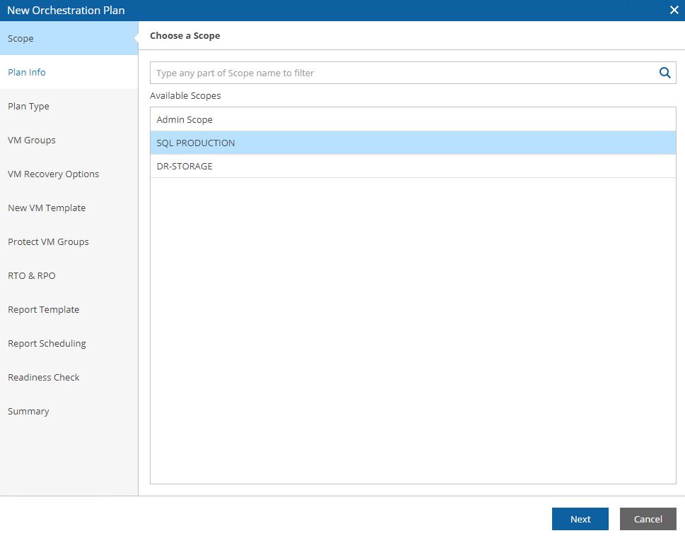
Picture 8
Picture 9 shows the detailed plan info and Picture 10 the plan type (next articles will deep how to set them up).
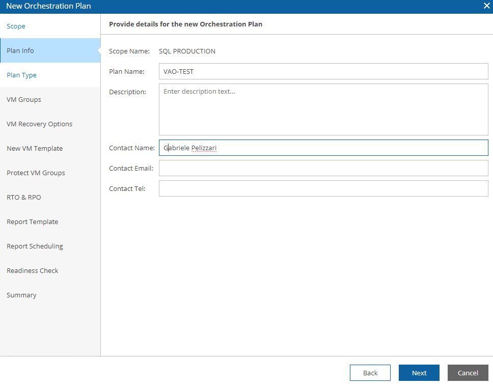
Picture 9
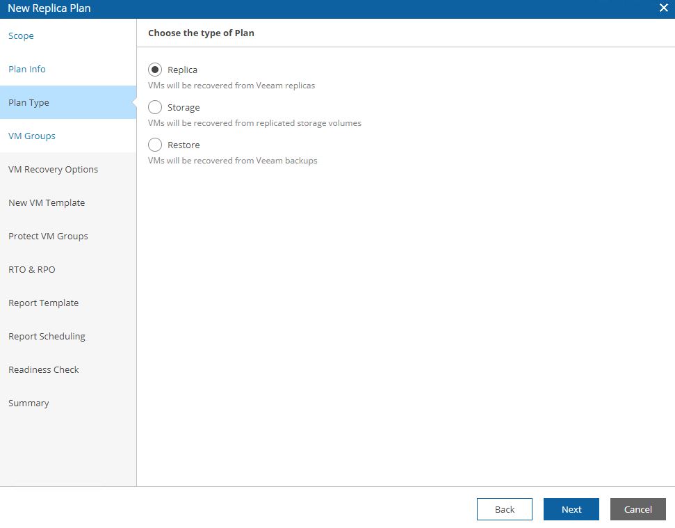
Picture 10
Pictures 11, 12, 13 show how it’s possibles to discover the VMs that belong to the group selecting VM group.
Picture 11
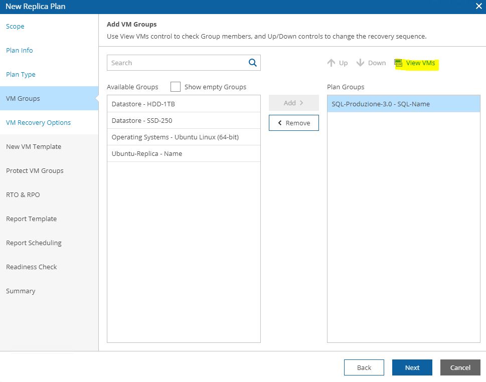
Picture 12
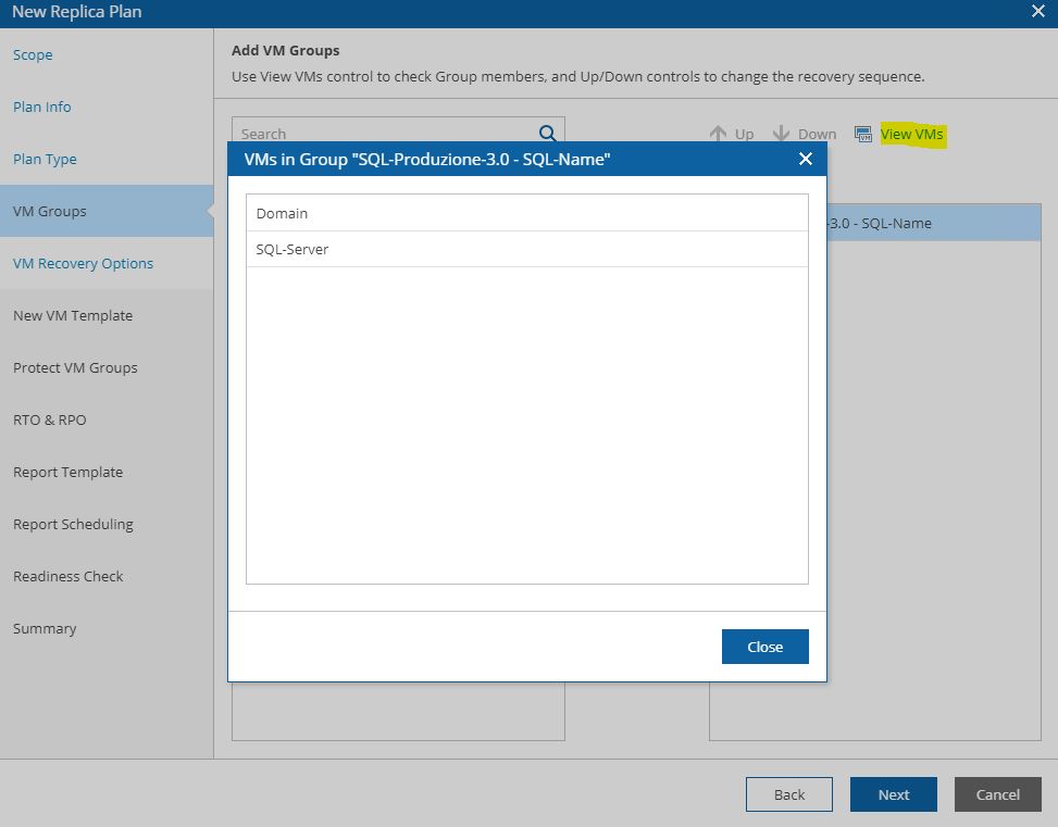
Picture 13
Picture 14 shows the control options for the DR plan. If something goes wrong the plan can be halted or not.
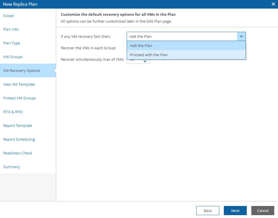
Picture 14
Picture 15 shows the steps, 16 the option to protect VMs switched on after the failover has been completed, 17 the RPO and RTO that the plan has to respect.
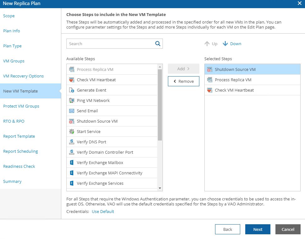
Picture 15
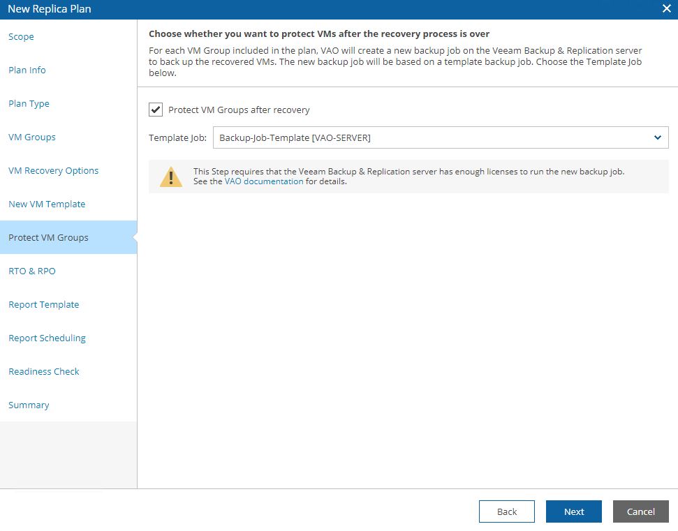
Picture 16
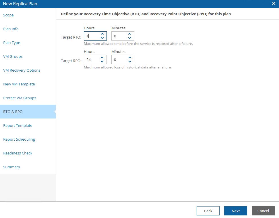
Picture 17
Picture 18 shows the template docs that will be used, while picture 19 shows a (for me) interesting mandatory check option.
Before doing any new activity the Readiness check analyzes that all components are correctly set up.
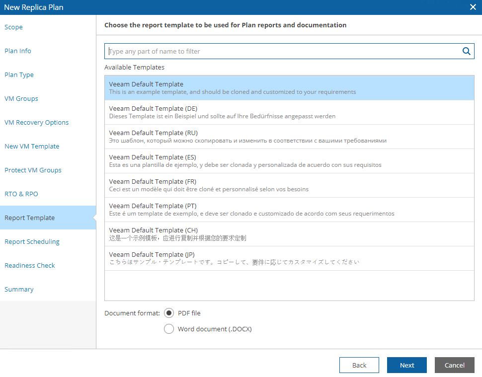
Picture 18
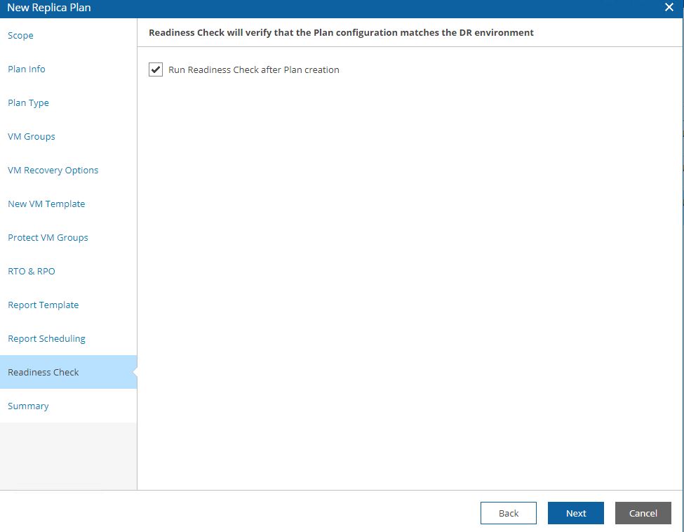
Picture 19
In my next article, I will cover two examples: DR-plan from Replica and DR-plan from backup. Keep in touch!
 Netapp – SnapMirror
 Picture 1
 Picture 2
 Picture 3
 Picture 4
 Picture 5
 Picture 6
 Picture 7
 Picture 10
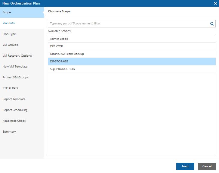 Picture 11
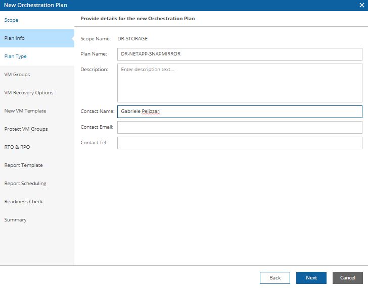 Picture 12
 Picture 13
 Picture 14
 Picture 15
 Picture 16
 Picture 17
 Picture 18
 Picture 19
 Picture 20
 Picture 21
 Picture 22
 Picture 23
 Picture 24
 Picture 25
 Picture 26
 Picture 27
 Picture 28
 Picture 29
 Picture 31
 Picture 32
 Picture 33
 Picture 34
 Picture 35